Aerospace Machining Tolerances Explained: Standards, GD&T, and First Article Inspection
Aerospace Manufacturing • Quality • Precision CNC
Aerospace Machining Tolerances Explained: Standards, GD&T, and First Article Inspection
Tolerances are the language of aerospace manufacturing. Get them wrong on the print and the part is over-spec'd and expensive; get them wrong in the shop and the part is non-conforming and rejected. This post explains the tolerance standards aerospace teams actually use, what counts as a "tight tolerance," and how First Article Inspection (FAI) verifies that a process can hold them.
Hanover, PA — If you are an engineer specifying a part, a procurement lead vetting a shop, or an OEM trying to read a supplier's quote intelligently, this is the foundation.
At a Glance
- Standard CNC machining holds ±0.005″ to ±0.010″ without special callouts — aerospace routinely requires tighter
- Tight tolerance machining means ±0.005″ or tighter; aerospace flight-critical features call out ±0.001″ or ±0.0005″
- GD&T (ASME Y14.5) controls form, orientation, location, and runout — not just linear size
- AS9102 First Article Inspection documents every characteristic on the print with actual measured values
- Olympus Machining holds aerospace tolerances on titanium, aluminum, and stainless with CMM-verified inspection
Standard Tolerances vs. Tight Tolerances
Most CNC machine shops, working without any specific callouts, will hold roughly ±0.005″ to ±0.010″ (±0.13 to ±0.25 mm) on linear dimensions. That is the baseline capability of the process across most materials and geometries.
In aerospace, that baseline is rarely enough.
- Tight tolerance machining typically means ±0.005″ (±0.13 mm) or tighter
- Aerospace flight-critical features routinely call out ±0.001″ (25 μm) or tighter on mating surfaces, bores, and locating features
- Precision-class aerospace work can specify ±0.0005″ (12.7 μm) or better on individual features — territory that rules out general-purpose shops and demands tight environmental and process control
The tighter the callout, the more it costs to produce — not because the cutter changes, but because everything around the cutter has to. Tooling wear, machine thermal stability, fixturing, inspection cadence, and operator experience all become first-order variables. Our quality assurance process is designed to manage these variables across every job.
The Standards That Define "Default" Tolerance
When a print does not call out an explicit tolerance for a dimension, a default standard fills the gap. The two most common in aerospace are:
- ISO 2768 — general tolerances for linear and angular dimensions on prints without individual callouts. Specifies four tolerance classes: fine, medium, coarse, and very coarse
- ISO 286 — tolerance system for linear sizes, especially shaft-and-hole fits
Both are useful for non-critical features, but neither captures form, orientation, location, or runout — and aerospace parts are full of features where those matter as much as size. That's where GD&T comes in.
GD&T: Why Aerospace Prints Look the Way They Do
Geometric Dimensioning and Tolerancing (GD&T), defined in ASME Y14.5, controls the functional tolerance of a feature — not just its size. Instead of plus/minus boxes, GD&T uses symbols, datums, and feature control frames to define how a feature must behave in the assembled part.
For aerospace parts, GD&T is the difference between a part that measures correctly and a part that fits correctly. A bore can be perfectly round and still be in the wrong place relative to its datum — GD&T is what catches that.
Common GD&T controls on aerospace prints:
- Position — where a feature sits relative to a datum reference frame
- Profile of a surface / profile of a line — how closely a contoured surface follows the design intent
- Flatness, parallelism, perpendicularity — orientation controls that matter for mating surfaces
- Concentricity, runout, total runout — for rotating components like shafts and bushings
A shop that quotes aerospace work without reading GD&T carefully will under-quote and over-promise. A shop that quotes it correctly will tell you exactly which features drive the cost. That is how OEMs evaluate CNC machine shops — by their ability to interpret the print.
First Article Inspection (FAI) and AS9102
Tolerances are only useful if you can prove the process holds them. That's the job of First Article Inspection (FAI) — and in aerospace, FAI is governed by AS9102.
AS9102 is the SAE-published standard that defines how aerospace suppliers document their first article. The current revision requires three forms:
- Form 1 — Part Number Accountability. Identifies the part, drawing revision, and supplier
- Form 2 — Product Accountability. Documents materials, special processes (heat treat, plating, NDT), and any sub-tier suppliers used
- Form 3 — Characteristic Accountability. A balloon-by-balloon record of every dimension and note on the print, with the actual measured value, the inspection method, and pass/fail
AS9102 is enforceable when invoked by the customer — and in aerospace, that's nearly every program. Triggers for a new FAI typically include first production from a new supplier, a drawing revision change, a process change, a tooling change, or a lapse in production over a defined period.
A shop that has a real FAI process — meaning a documented procedure, calibrated inspection equipment, traceable measurement records, and an inspector who can balloon a print without coaching — is a very different supplier than one that "does FAI when asked." Our quality management system (QMS) is built around this kind of documented, repeatable process control.
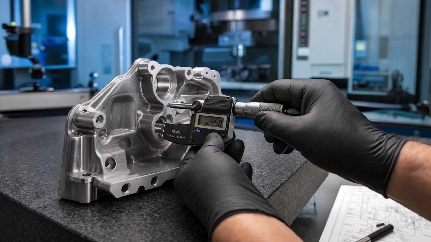
Tolerances and the Equipment That Holds Them
Holding ±0.001″ across a production run is not just a cutter problem. It is a system problem:
- Machine thermal stability. A spindle that grows 0.0005″ as it warms up will eat the tolerance budget by itself
- Fixture rigidity and repeatability. A setup that flexes 0.0002″ under cutting load is a setup that produces 0.0002″ of variation
- Tool wear monitoring. Tools wear, and the wear shows up as drift in the dimension. A shop that's holding ±0.001″ is monitoring that drift
- Inspection at the right cadence. First-piece, in-process, and final — measured on equipment with appropriate accuracy reserve (typically a 4:1 or 10:1 ratio between measurement uncertainty and tolerance)
At Olympus Machining, our Haas HM-4930 CMM handles dimensional verification, FAI, and in-process checks. Combined with our QMS and ITAR-aligned process controls, that is what lets us hold aerospace tolerances on titanium, aluminum, and stainless components from prototype through production.
What This Means for Buyers
If you are sourcing aerospace components, ask your suppliers three things:
- What tolerance class do you hold by default, and what does it cost to step tighter? A shop that can answer this clearly understands its own process capability
- Walk me through your AS9102 FAI documentation on a recent program. A shop that has actually done FAI can show you the forms
- What is your inspection equipment, and when was it last calibrated? Calibrated CMM, calibrated gauges, and a documented calibration schedule are the table stakes
The answers tell you whether the shop is built for aerospace work or hoping to pick up the occasional aerospace job. For more on supplier evaluation, see how to vet a CNC machine shop in Pennsylvania.
Explore our precision CNC machining services, learn about the materials we machine, see the industries we serve, or read about aerospace CNC machining in Pennsylvania.
Contact Olympus Machining
Olympus Machining LLC
639 Frederick St, Suite 1
Hanover, PA 17331
Phone: (717) 634-5094
Website: www.olympusmachining.com
Google Business Profile:
View on Google
Request a Quote:
Submit a project
About Olympus Machining
Olympus Machining LLC is a precision CNC machining shop located in Hanover, Pennsylvania. As a dedicated CNC machining shop and reliable machining vendor, we provide CNC milling, CNC turning, and prototype-to-production services for OEMs and manufacturers nationwide.
Related Articles
Related Capabilities from Olympus Machining
AS9102 First Article Inspection
AS9102 Rev C FAI services with Forms 1, 2, and 3 documentation.
Full FAI vs Partial FAI (PFAI)
When a PFAI is acceptable and when a Full FAI is required.
Balloon Drawings for AS9102 Form 3
Balloon drawing preparation for Form 3 characteristic accountability.
CMM Inspection Services
Coordinate measuring machine verification with full reporting.
Submit Your Project for Review
Contact Olympus Machining to discuss your CNC machining requirements.