STEP Files for CNC Machining Quotes: Why File Format Decides How Fast and Accurate Your RFQ Comes Back
RFQ Workflow • CAD Files • Field Guide
STEP Files for CNC Machining Quotes: Why File Format Decides How Fast and Accurate Your RFQ Comes Back
A practical guide to why STEP (.step / .stp) is the file format precision CNC machine shops need to quote your parts — what to send, what to avoid, and how a U.S.-based precision CNC shop in Hanover, Pennsylvania actually reviews a drawing package before returning a quote.
TL;DR
- STEP (AP214 or AP242, .step / .stp) is the universal neutral CAD format every precision CNC shop's CAM software can open with full solid geometry intact.
- STL files are mesh approximations meant for 3D printing — they lose true edges, holes, and curved surfaces, and they cannot be reliably machined or measured.
- A complete quote package is a STEP file plus a 2D drawing (PDF) with tolerances, GD&T, material specification, surface finish, and quantity. The drawing governs; the model is the geometry source.
- Sending a STEP + PDF together typically returns a quote in 24–48 hours. Sending screenshots, STL files, or native files the shop cannot open adds days of back-and-forth before quoting can even start.
Why CNC machine shops ask for STEP files specifically
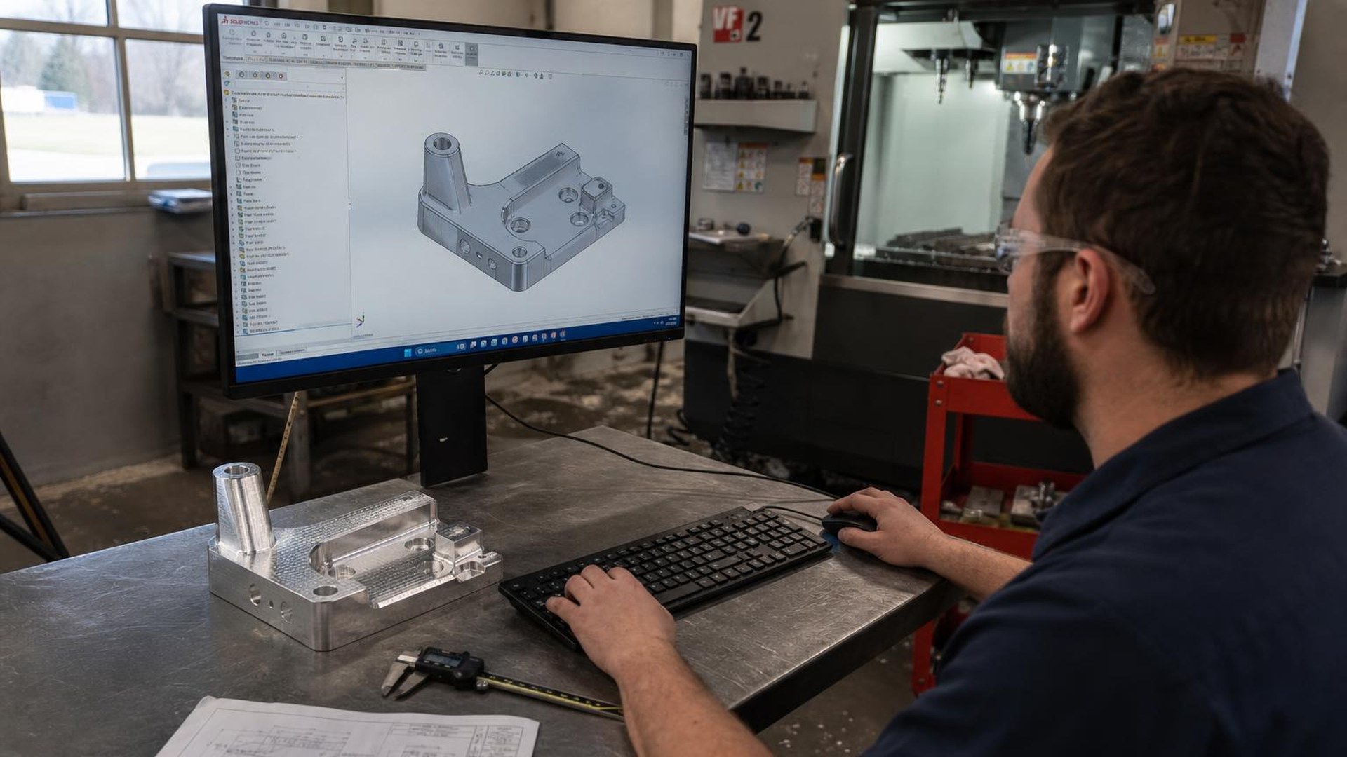
A CNC machine shop quotes a part by loading its 3D model into CAM software, identifying the features (pockets, bores, threads, profiles), and estimating the cycle time on a specific machine with a specific tool list. That workflow requires true solid geometry — analytical surfaces, exact edges, accurate hole diameters, and verifiable wall thicknesses. STEP (ISO 10303, typically AP214 for mechanical parts or AP242 for the modern protocol with PMI) is the neutral file format that preserves all of that across CAD systems.
Every serious CAM package — Mastercam, Fusion 360, Esprit, NX CAM, HyperMill, GibbsCAM — opens STEP cleanly. Native files (SolidWorks .sldprt, Inventor .ipt, Creo .prt, CATIA .CATPart) often open too, but only if the shop happens to license the same CAD seat at a compatible version. STEP eliminates that compatibility risk entirely. That is why a precision CNC shop will ask for it before any other format.
Olympus Machining is a U.S.-based precision CNC machine shop located in Hanover, Pennsylvania that quotes new part numbers daily for OEM engineering and procurement teams. The single biggest factor in how fast we can return an accurate quote is the file package the customer sends.
CAD file formats ranked for CNC quoting
Not every file a customer sends is usable. Here is how the common formats rank from a machine shop's quoting desk:
- STEP (.step / .stp) — preferred. Neutral, lossless solid geometry. AP214 covers mechanical assemblies; AP242 adds embedded GD&T (PMI). Opens in every CAM system.
- Native CAD (.sldprt, .ipt, .prt, .CATPart) — usable if compatible. Often opens in modern CAM but version mismatches are common. Always pair with a STEP export.
- Parasolid (.x_t / .x_b) — equivalent to STEP for most shops. A neutral solid format; fine as a primary file. Pair with a 2D drawing.
- IGES (.igs / .iges) — legacy, surface-based. Still readable but often imports as disconnected surfaces, not a solid. Acceptable as a backup; STEP is preferred.
- 2D DXF / DWG — only for sheet-metal flat patterns and 2.5D profiles. Not sufficient for 3-axis or 5-axis milled parts.
- STL (.stl) — not acceptable for machining. STL is a triangulated mesh approximation for 3D printing. Holes become faceted polygons, cylinders become 24-sided prisms, and tolerances cannot be enforced. A shop cannot quote a precision machined part from STL alone.
- PDF or screenshots only — not quotable. Without a 3D model, the shop must reverse-engineer geometry from dimensioned views, which adds engineering time and risk to the quote.
Why STL files are the most common quoting bottleneck
STL is the file format engineers most often send by mistake because it is the default export for desktop 3D printers and many parametric modelers' "share" buttons. The format stores a part as a closed mesh of triangles — an approximation of the true surface. For a printed prototype that is acceptable; for a machined production part it is not.
Three specific problems make STL unsuitable for CNC quoting:
- Lost analytical features. A ∅0.250″ reamed hole exported as STL becomes a polygon ring of 32 or 64 triangles. The CAM system cannot recognize it as a hole, so it cannot select the correct drill, reamer, or boring cycle.
- Lost tolerance intent. Mesh deviation from the true surface (often 0.003″–0.010″ depending on export settings) exceeds typical machining tolerances. There is no way to inspect a machined part back to an STL with any meaningful accuracy.
- Lost edges. Filleted edges, chamfers, and tangent transitions blend into faceted strips. Tool selection and toolpath generation degrade accordingly.
When a quote desk receives an STL with no other files, the result is always the same: a request back to the customer for a STEP file and a drawing. That round trip costs one to three business days before quoting can even begin.
What a complete RFQ package looks like
A precision CNC shop can quote quickly and accurately when the package contains every piece of information needed to plan the job. For most parts, that is:
- STEP file (.step or .stp) — AP214 or AP242, one file per unique part number.
- 2D drawing (PDF) — dimensioned views with explicit tolerances, GD&T per ASME Y14.5, surface finish callouts (Ra), material specification (e.g. AL 6061-T6 per AMS-QQ-A-200/8), heat treat, coating or finish (anodize type and class, passivation, plating), and part number / revision.
- Quantities and delivery requirement — prototype quantity (1–10), pilot lot (25–100), or production lot (100+), plus the required delivery date.
- Quality and documentation requirements — AS9102 First Article Inspection, CMM inspection report, material certifications (mill test reports), Certificate of Conformance, source inspection requirements.
- Industry and compliance flow-downs — ITAR, DFARS 252.204-7012, NIST SP 800-171, CMMC level, NADCAP special processes (heat treat, NDT).
When all of the above arrives together, a quote turns around in 24 to 48 hours for most precision parts. When pieces are missing, every back-and-forth adds a business day. The shape of a fast RFQ workflow is documented further in our prototype-to-production scaling guide.
The drawing governs — the STEP file is the geometry source
A common engineering question is whether the 2D drawing is still needed when the 3D model is fully dimensioned. For production machining, the answer is yes. The drawing remains the authoritative reference document for tolerances, GD&T, surface finish, and inspection requirements. The STEP file supplies the geometry the CAM system mills from, but the drawing is what the inspector measures against and what the AS9102 First Article Inspection report cites line by line.
Model-Based Definition (MBD) with PMI embedded in a STEP AP242 file is increasingly common in aerospace and defense programs, but most precision CNC shops still expect a 2D drawing alongside the model. If the program is fully MBD, state that in the RFQ and confirm the shop can consume PMI from the file. Olympus Machining can.
How to export a clean STEP file from common CAD systems
Most CAD systems export STEP through File → Save As or File → Export. A few defaults are worth setting deliberately:
- SolidWorks: Save As → STEP AP214 (or AP242 if exporting PMI). Under Options, enable Export sketch entities off, Split periodic faces off.
- Autodesk Inventor: Export → CAD Format → .stp. Application protocol AP214 for parts and assemblies.
- Fusion 360: File → Export → STEP Files (*.stp). Fusion writes AP214 by default.
- PTC Creo: File → Save As → STEP. Set step_export_format to AP214 in config.
- CATIA: File → Save As → STEP. AP214 covers mechanical parts; AP242 for assemblies with PMI.
- Siemens NX: File → Export → STEP 214 for parts.
For assemblies, exporting either a single STEP file containing the assembly or one STEP per component is acceptable. Confirm the shop's preference if the assembly contains hundreds of parts; one combined STEP is usually easier to review on quote.
What a shop actually does with your STEP file during quoting
When a STEP file arrives at Olympus Machining, the quote workflow is repeatable:
- Import and verify the solid. The CAM system loads the file and confirms a closed, manifold solid (no surface gaps). Bounding-box dimensions and part volume are checked against the drawing.
- Material and stock selection. The drawing specification drives material; the model drives the stock size. Aluminum 6061 and 7075, stainless 303/304/316/17-4 PH, Ti-6Al-4V, and Inconel 718 are routine here — see our full materials capabilities page.
- Feature identification. The estimator reviews bores, threads, profile mills, and any features that demand 4th- or 5th-axis access. This drives the machine selection — a 3-axis VMC, a 5-axis mill, or a Swiss-style lathe.
- Tolerance and GD&T review. Tight true-position callouts, surface finish below 32 Ra, or concentricity better than 0.0005″ TIR drive process planning — in-process probing, finishing tool selection, and CMM inspection time.
- Cycle time estimate and quote build. Roughing and finishing toolpaths are simulated, cycle time is captured, and shop rate is applied alongside material cost, inspection time, and any outside processing (heat treat, anodize, NDT).
Every one of those steps depends on a usable solid model. A STEP file enables all five; an STL blocks every one of them.
Common RFQ mistakes that delay quoting
- STL only. Triggers a request for STEP. Add one to three days.
- Screenshot of a CAD window. Not quotable without a model. Add three to five days while drawings are reconstructed.
- Drawing with no tolerances. Forces the shop to assume default block tolerances (typically ±0.005″), which may price the part too low or too high. Always include a title-block tolerance and explicit callouts on critical features.
- No material callout. "Aluminum" is not a specification. State the alloy and temper (6061-T6, 7075-T651) and the governing material standard (AMS, ASTM, QQ-A).
- Missing quantity. Per-piece price changes significantly between a quantity of 1 and a quantity of 50. State both prototype and production quantities if known.
- Outdated revision. Send the latest revision of the STEP and the drawing together and call out the revision on both. Mixed revisions in an RFQ package are a common source of scrapped first articles.
Sending files securely for ITAR or controlled programs
For ITAR-controlled, DFARS-regulated, or other controlled-unclassified-information (CUI) drawing packages, file transfer matters as much as file format. Email attachments of CUI are not permitted under most DFARS 252.204-7012 / NIST SP 800-171 flow-downs. Use the receiving shop's secure portal or an approved file-transfer system. Olympus Machining accepts controlled file packages through the secure project submission flow on the website; see the DFARS compliance overview for context on which flow-downs apply.
Frequently asked questions
What file format do CNC machine shops want for quoting?
STEP (.step or .stp), AP214 or AP242, paired with a 2D drawing in PDF. STEP is the neutral 3D format every CAM system reads cleanly, and the drawing is the authoritative source for tolerances, GD&T, surface finish, and material specification.
Can a machine shop quote a part from an STL file?
Not reliably. STL is a triangulated mesh meant for 3D printing — holes, cylinders, and curved surfaces are approximated as polygons, so the CAM system cannot recognize machining features or enforce tolerances. A precision shop will request a STEP file before quoting.
Do I still need a 2D drawing if I send a 3D model?
Yes for production parts. The drawing remains the authoritative document for tolerances, GD&T, surface finish, and inspection. Model-Based Definition (MBD) with PMI embedded in a STEP AP242 file is acceptable on programs that have formally adopted it, but most CNC shops still expect a 2D drawing alongside the model.
What is the difference between STEP AP214 and AP242?
AP214 is the established protocol for mechanical part and assembly geometry. AP242 is the modern successor that adds embedded Product Manufacturing Information (PMI) — GD&T, surface finish, and notes carried in the 3D model. Both are universally readable; AP242 enables a true MBD workflow when both customer and shop support PMI.
How fast can I get a quote back if I send a STEP file and drawing?
For most precision parts, 24 to 48 hours. Highly complex 5-axis parts, large assemblies, or programs requiring multiple outside processes (heat treat, NDT, anodize) may run 3 to 5 business days. Missing files or unclear specifications add to that time.
Ready to send a STEP file for quote?
Send the STEP file, 2D drawing, material specification, and quantity. We will return a quoted package with tolerance review and lead time, typically inside 24 to 48 hours.
Explore Olympus Machining's CNC milling, CNC turning, materials capabilities, aerospace and defense industry page, AS9102 First Article Inspection, and prototype-to-production scaling.
Contact Olympus Machining
Olympus Machining LLC
639 Frederick St, Suite 1
Hanover, PA 17331
Phone: (717) 634-5094
Website: www.olympusmachining.com
Google Business Profile: View on Google
Request a Quote: Submit a project
About Olympus Machining
Olympus Machining LLC is a precision CNC machining shop located in Hanover, Pennsylvania. As a dedicated CNC machining shop and reliable machining vendor, we provide CNC milling, CNC turning, and prototype-to-production services for OEMs and aerospace manufacturers nationwide. ITAR registered, CMMC Level 1, CAGE 9V9P0.
Related Capabilities from Olympus Machining
CNC Milling Services
Multi-axis precision milling for complex geometries and tight tolerances.
CNC Turning Services
Precision lathe machining for shafts, bushings, and cylindrical components.
Quality Assurance & Inspection
First article inspection, CMM verification, and full documentation packages.
Prototype to Production
Seamless transitions from prototype validation through full-scale production.
Submit Your Project for Review
Contact Olympus Machining to discuss your CNC machining requirements.