CMM Inspection Checklist for Aerospace CNC Parts: An AS9102-Aligned Field Guide
Quality Assurance • Aerospace • CMM Inspection
CMM Inspection Checklist for Aerospace CNC Parts: An AS9102-Aligned Field Guide
A working checklist for engineers and quality leads who own first article inspection on aerospace and defense CNC machined parts. Based on AS9102 Rev C, GD&T per ASME Y14.5, and shop-floor practice on a Haas HMM 430 CMM.
TL;DR
- A defensible CMM inspection package for an aerospace CNC part has three artifacts: a balloon drawing, an alignment and datum strategy, and a measurement report keyed back to the balloons.
- AS9102 Rev C Form 3 requires every characteristic on the drawing — dimensional, GD&T, notes, materials, and processes — to be ballooned and reported once. Missing or merged balloons are the most common rejection reason.
- The datum reference frame on the CMM must match the print exactly. A and B flipped, or a secondary datum picked from the wrong feature, invalidates every position and profile callout.
- Probe selection, qualification, and temperature stabilization decide whether your numbers are real. A 1-degree-Fahrenheit swing on a 6-inch aluminum part moves a dimension by roughly 0.00008 inches.
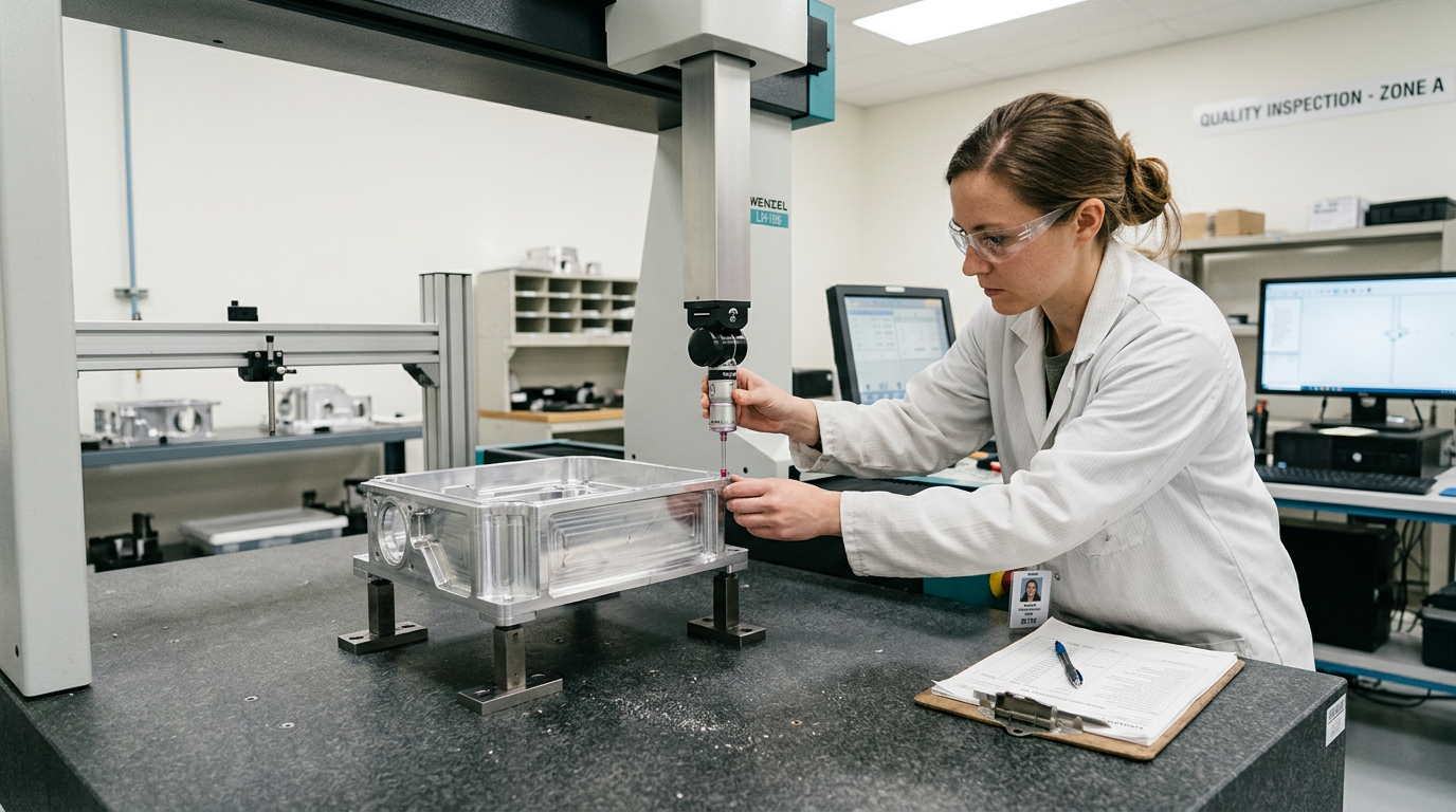
Before the part hits the CMM
Half of a clean CMM run is decided before the part is loaded. Work through this pre-inspection checklist on every AS9102 First Article and on any in-process inspection where dispositions will rely on the report.
- Drawing revision lock. Confirm the inspector, machinist, and CMM programmer are all working from the same revision and that any redline change orders have been incorporated.
- Balloon drawing complete. Every dimension, GD&T frame, surface finish, note, material spec, and finish callout has a unique balloon. Sub-features (chamfer angle and chamfer width) get separate balloons.
- AS9102 forms started. Form 1 (part identification), Form 2 (materials and processes), and Form 3 (characteristic accountability) opened and pre-populated from the drawing.
- Datum reference frame defined. Primary (3 points), secondary (2 points), tertiary (1 point). Confirm the datum surfaces are not damaged, deburred, or coated in a way that would shift the alignment.
- Probe and tip qualified. Star, stylus, or extension qualified the same day. Probe diameter recorded in the report header.
- Part temperature stabilized. Soak time on the granite long enough to match the room — typically 30 to 60 minutes for a fist-sized aluminum part, longer for steel or titanium with mass.
- Fixture repeatability checked. If a fixture is used, confirm it is the same fixture noted in the routing and that the part seats without rocking.
Alignment strategy: matching the print's DRF
The single most common cause of false-fail CMM reports on aerospace work is an alignment that does not match the drawing's datum reference frame. Position tolerance, profile of a surface, and runout are all measured against a frame — if the frame is wrong, the numbers are wrong, even if the part is good.
Build the alignment in the same order the print calls out: A locks the part down, B controls rotation about A, C controls translation. On a typical aerospace bracket with A = bottom face, B = a side, C = a hole, that means probing a plane on A first, then a line on B, then a point on C. Reversing this — using C as a primary datum because the hole is easy to probe — invalidates every position callout downstream.
Datum targets, when called out on the print, are non-negotiable. A 3-2-1 datum target scheme with explicit X, Y, Z coordinates and target sizes must be probed at those exact locations, not at the centers of the nominal datum features.
Measurement strategy by callout type
How a feature is probed changes what the CMM reports. The checklist below is the working rule set used on aerospace and defense CNC parts at Olympus Machining.
- Diameters and bores. Minimum five points per circle, three circles minimum on a bore that has a length-to-diameter ratio over one. Report the best-fit circle, the minimum-circumscribed circle for go/no-go inspection of pins, and the maximum-inscribed circle for bores.
- Position of holes. Reported as a true position diameter in the datum reference frame. Confirm material condition modifier — MMC, LMC, or RFS — is applied as drawn. Forgetting MMC gives away bonus tolerance you legitimately earned.
- Profile of a surface. Surface profile sampled at the density the print implies. A profile of 0.005 on a 4-inch curved surface with no sample-density note still needs enough points to characterize the form, not just three corners.
- Flatness. Minimum nine points on small surfaces, more for larger ones. Distribute the points across the surface, not in a single row.
- Perpendicularity and parallelism. Measured against the called-out datum, not against the part. A perpendicularity to A measured from the table surface is not a valid report.
- Concentricity vs runout. Read the print carefully — concentricity and total runout are not interchangeable. Concentricity is rarely the correct callout and is being phased out in ASME Y14.5-2018; if the print uses it, report it as drawn but flag for engineering review.
- Thread features. CMM probes do not inspect thread pitch diameter — use gages and record the gage ID and calibration date in the report. Thread location can be probed using the minor diameter.
Reporting and traceability
The CMM report is evidence. For aerospace and defense customers it has to be self-contained — anyone opening it months later should be able to reconstruct exactly what was measured and how.
- Header includes part number, revision, serial or lot, operator, CMM ID, probe configuration, software version, temperature, and date.
- Every reported characteristic has a balloon number that matches the AS9102 Form 3 row exactly. No re-numbering between the balloon drawing and the report.
- Out-of-tolerance conditions are flagged at the report level, not buried inside a results column. The disposition (accept, rework, scrap, MRB) is signed and dated.
- Gage R&R or measurement system analysis referenced for any tolerance tighter than 0.0005 inches.
- Raw probe data retained per the customer's contractual retention window — typically seven years for aerospace, longer for defense programs under DFARS 252.204-7012.
Common rejection reasons and how to prevent them
- Balloon drawing incomplete — notes and material specs missing.
- Form 3 actual value listed as "in tolerance" instead of the measured number.
- Position callout reported without the correct material condition modifier.
- Datum reference frame in the CMM program does not match the drawing.
- Thread pitch diameter probed on the CMM instead of gaged.
- Surface finish measured by a different instrument with no traceability noted.
- Material certification attached for a different lot than the part.
- Inspector signature missing on Form 1.
FAQ
Does AS9102 require a CMM?
No. AS9102 requires that every characteristic be measured with appropriate equipment and reported in Form 3. A CMM is the standard for complex geometric callouts, but micrometers, height gages, optical comparators, and pin gages are all acceptable when traceable.
How many points per feature is "enough"?
Enough to characterize the feature's form, not just its size. Five points on a circle is a minimum, not a target. For profile and form callouts, the sample density should be high enough that adding more points does not change the result.
Can the CMM report be the only inspection record?
For most aerospace parts, no. Threads, surface finish, hardness, and material identity all require evidence outside the CMM. The CMM report is one section of the AS9102 package.
What temperature should the room be at?
Standard metrology rooms hold 68 degrees Fahrenheit plus or minus 2. Shop-floor CMMs can hold tighter tolerances on a stabilized part — what matters is the part and the master are at the same temperature when probed.
Explore Olympus Machining's CMM inspection services, our AS9102 First Article Inspection process, balloon drawing preparation, and the difference between full FAI and partial FAI.
Contact Olympus Machining
Olympus Machining LLC
639 Frederick St, Suite 1
Hanover, PA 17331
Phone: (717) 634-5094
Website: www.olympusmachining.com
Request a Quote: Submit a project
About Olympus Machining
Olympus Machining LLC is a precision CNC machining shop located in Hanover, Pennsylvania. As a dedicated CNC machining shop and reliable machining vendor, we provide CNC milling, CNC turning, and prototype-to-production services for OEMs and manufacturers nationwide. ITAR registered, CMMC Level 1, CAGE 9V9P0.
Related Articles
Related Capabilities from Olympus Machining
CMM Inspection Services
Coordinate measuring machine verification with full reporting.
Quality Assurance & Inspection
First article inspection, CMM verification, and documentation packages.
AS9102 First Article Inspection
AS9102-aligned FAI services for aerospace and defense parts.
Precision CNC Machining
Hanover, PA precision CNC shop for tight-tolerance aerospace and defense parts.
Submit Your Project for Review
Contact Olympus Machining to discuss your CNC machining requirements.