CMM Inspection and Quality Assurance Protocols for Aerospace CNC Parts: A Technical Field Guide
Metrology • CMM • Hanover, PA
CMM Inspection and Quality Assurance Protocols for Aerospace CNC Parts: A Technical Field Guide
Olympus Machining is an ITAR-registered precision CNC machine shop in Hanover, Pennsylvania producing AS9102-documented aerospace and defense parts on Haas mills and Chien Wei live-tool turning centers.
This guide documents the metrology stack, calibration practices, and dimensional reporting protocols used at Olympus to deliver airworthy CNC parts to prime contractors and Tier 1/2 aerospace subtiers.
At a glance
- Two CMMs in-house: Haas HMM 430 (3-axis) and Chien Wei CWB-450-CNC (CNC + rotary), both NIST-traceable and annually calibrated.
- Inspection deliverables: AS9102 Rev C Form 1/2/3, balloon-numbered drawings, CMM dimensional reports, FAI-equivalent reports, and SPC data on request.
- Process: characteristic accountability begins at the drawing review stage — every callout is ballooned, programmed, and signed off before parts ship.
- ITAR-controlled work routes through access-controlled folders, controlled prints, and CMMC Level 1 cybersecurity practices per FAR 52.204-21.
Why CMM Inspection Is the Backbone of Aerospace Quality
Aerospace part acceptance is not a question of whether a feature looks right — it is a question of whether every dimensional, geometric, and surface characteristic on the drawing has been measured against an artifact traceable to a national standard, and whether that measurement has been recorded in a form a quality engineer can audit twelve months later. Coordinate measuring machines (CMMs) are the only practical way to discharge that obligation across the GD&T callouts typical of aerospace prints: true position, profile of a surface, cylindricity, perpendicularity, parallelism, and coaxiality applied at maximum-material or regardless-of-feature-size conditions.
Generic machine shops can hit dimensions with hand tools. They cannot reliably hit them while also producing a defensible inspection record that survives a prime-contractor audit, a customer source inspection, or a CAPA investigation triggered by a downstream non-conformance. CMM-centered quality programs close that gap.
The Olympus Metrology Stack
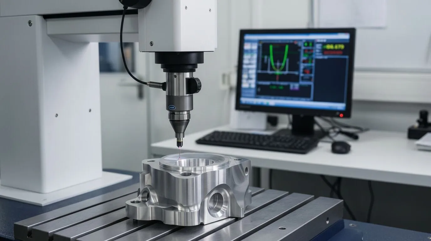
Haas HMM 430 — 3-Axis CMM
Touch-probe coordinate measuring machine with a 400 × 300 × 300 mm envelope. Used for prismatic milled work — brackets, housings, weapon mounts, antenna fixtures — where the dominant features are linear dimensions, hole patterns, position tolerances, flatness, and parallelism. Programmed in PC-DMIS-equivalent software with characteristic numbers tied directly to the balloon-numbered drawing, so the resulting Form 3 reads back in the customer's own callout order.
Chien Wei CWB-450-CNC — CNC CMM with Rotary Axis
Full CNC CMM with a 450 × 500 × 400 mm envelope and rotary-axis support for shaft work, turned components, and complex 5-axis milled geometries. Cycle-based programming enables repeatable lot inspection — every fifth part, every part, or full-lot sampling depending on the customer's Quality Plan — without operator-introduced variation between cycles.
Supplemental Hand-Tool Inventory
Calibrated micrometers (ID/OD/depth), digital calipers, height gages, granite surface plates, thread plug and ring gages, pin gage sets to ±0.0002", and bore gages. Hand tools cover features outside CMM access (deep bores, thread pitch verification, surface-finish comparisons) and provide redundant verification on critical features. Every tool is on a documented calibration recall schedule with certificates kept on file.
From Drawing to Dimensional Report: The Workflow
- Drawing review. Before programming begins, the print is reviewed for tolerance stack-up risk, GD&T interpretation ambiguity, and any callouts that require special tooling or process routing. DFM questions go back to the customer in writing.
- Ballooning. Every dimensional, geometric, material, and note characteristic is sequentially numbered on a controlled-print PDF. The ballooned drawing becomes the canonical reference for FAI Form 3, the CMM program, and any subsequent CAPA investigation.
- CMM programming. Probe paths are written against the ballooned characteristics. Each measurement routine is verified on a representative coupon before first-article runs.
- First Article Inspection (AS9102 Rev C). First piece off the production setup is measured against every characteristic. Form 1 (part identification), Form 2 (raw material and special processes), and Form 3 (characteristic accountability) are issued as the acceptance gate.
- In-process verification. SPC sampling on critical-to-quality features during the production run. Out-of-trend results trigger a hold and a documented review before the next part is cut.
- Final dimensional report. Issued per customer requirement — full Form 3 every part, sampling plan, or customer-template summary. Reports are delivered through the customer's specified channel (controlled email, customer portal, or supplier extranet) and retained internally for the required record-keeping period.
Calibration and Traceability
Both CMMs are calibrated annually by an accredited calibration service against NIST-traceable artifacts. Calibration certificates are made available on request as part of supplier qualification packages and prime-contractor audit responses. Hand tools fall under the same controlled calibration program, with recall intervals tightened on tools used for critical-feature verification.
Material certifications follow the same chain of custody. Raw stock is received with mill test reports tied to heat and lot, those reports are linked in the job record to the parts produced, and the FAI Form 2 carries the mill cert through to the customer. Special processes (anodize, passivation, plating, heat treat) are sourced from suppliers with valid certifications that are flowed down on the purchase order and verified on receipt.
GD&T Callouts Aerospace Engineers Most Often Get Wrong
Most rejected FAI packages do not fail because the part is bad — they fail because the report does not document the right thing in the right way. A few patterns recur:
- True position called RFS when MMC is intended. Bonus tolerance from the MMC modifier changes the accept/reject envelope materially. If the drawing says RFS, the CMM program must score it RFS, even if "everyone knows" MMC was meant.
- Profile of a surface with no datum reference frame. Profile without datums is a form tolerance, not a location tolerance. CMM reports must measure it as called, not as the engineer wishes they had called it.
- Composite position tolerances reported as single segments. Composite frames have a pattern-locating tolerance zone (PLTZF) and a feature-relating tolerance zone (FRTZF). Both must be reported separately on Form 3.
- Datum simulators built from the wrong feature. Establishing a datum from a chamfered edge, a broken corner, or a feature with form error invalidates every downstream measurement. The DRF must be built from the features the drawing names, in the order it names them.
- Surface finish stated without lay or filter cutoff. Ra alone is incomplete; a Ra 32 callout with no cutoff and no lay direction is ambiguous and will be flagged by a thorough source inspector.
Inspection Cadence by Program Phase
| Phase | Typical inspection | Deliverable |
|---|---|---|
| Prototype | Full CMM of critical features | Dimensional report |
| First Article | 100% characteristic accountability | AS9102 Rev C Form 1/2/3 |
| Pilot run | First piece + sampling per Quality Plan | FAI + sample report |
| Production | SPC on CTQ features, FAIR on revision changes | CoC + dimensional summary |
| Source inspection | Joint witness measurement | Signed acceptance record |
CMMC Level 1 and the Inspection Record
For ITAR-controlled and CMMC-scoped work, dimensional reports are not just quality artifacts — they are controlled documents. Olympus handles them under the same access controls as the underlying engineering drawing: stored in access-restricted folders, transmitted through customer-specified channels, and retained per the customer's record-keeping clause. CMMC Level 1 practices per FAR 52.204-21 apply: identified users, controlled access, sanitized media, and access logs sufficient to support a flow-down audit.
Frequently Asked Questions
What is a CMM and why is it required for aerospace work?
A coordinate measuring machine is a touch-probe (or non-contact) instrument that records the X/Y/Z position of points on a part surface and computes dimensional and geometric features from those points. It is required for aerospace work because GD&T callouts like true position, profile of a surface, and coaxiality cannot be measured reliably with hand tools, and because aerospace customers expect a digital, repeatable, auditable record of every characteristic on the print.
What is the difference between a CMM dimensional report and an AS9102 FAI?
A CMM dimensional report documents measurements against drawing requirements. An AS9102 First Article Inspection Report is the full quality acceptance package — Form 1 (part identity), Form 2 (raw material and special process accountability), and Form 3 (characteristic accountability) — that establishes the production baseline. The CMM report typically becomes the data source for Form 3 but the AS9102 package adds material traceability, process accountability, and a signed acceptance record.
Do you do source inspection?
Yes. Customer representatives can witness final acceptance on-site at the Hanover facility. CMM cycles are repeatable, so a witnessed run is dimensionally equivalent to the unwitnessed runs that follow.
Can you produce inspection reports in our company's template?
Yes. Customer-specified templates, customer portals, and prime-contractor formats are supported in addition to standard AS9102 Rev C forms. Send the template at the quoting stage so the inspection program can be tailored to output it directly.
How are calibration certificates handled for supplier audits?
Calibration certificates for both CMMs and all critical hand tools are NIST-traceable and available on request. They are provided as part of the supplier qualification package and re-issued annually after recalibration.
Contact
Olympus Machining LLC
639 Frederick Street, Suite 1, Hanover, PA 17331
(717) 634-5094 · info@olympusmachining.com
ITAR Registered · CAGE 9V9P0 · CMMC Level 1 · NAICS 332710
About Olympus Machining
Olympus Machining is a U.S.-based precision CNC machining shop located in Hanover, Pennsylvania. The shop produces aerospace, defense, robotics, and medical components on Haas vertical machining centers and a Chien Wei CWB-450-CNC live-tool turning center, with in-house CMM dimensional inspection and AS9102 First Article Inspection as standard deliverables.
Related: CMM Inspection Services · AS9102 First Article Inspection · Balloon Drawings for AS9102 Form 3 · Quality Assurance · Aerospace & Defense Machining · Credentials & Capability Statement
Related Articles
Related Capabilities from Olympus Machining
CMM Inspection Services
Coordinate measuring machine verification with full reporting.
Quality Assurance & Inspection
First article inspection, CMM verification, and documentation packages.
AS9102 First Article Inspection
AS9102-aligned FAI services for aerospace and defense parts.
Precision CNC Machining
Hanover, PA precision CNC shop for tight-tolerance aerospace and defense parts.
Submit Your Project for Review
Contact Olympus Machining to discuss your CNC machining requirements.