Surface Finish Requirements for Tight-Tolerance CNC Machining: Ra, Rz, and What Aerospace & Defense Buyers Actually Need to Specify
Precision CNC Machining • Surface Metrology • Aerospace & Defense
A ±0.0005-inch tolerance means nothing if the surface finish is wrong. This is what an aerospace or defense buyer actually needs to know about Ra, Rz, and surface texture before releasing an RFQ.
Hanover, PA — Olympus Machining LLC · Haas HMM 430 CMM · Chien Wei CWB-450-CNC · ITAR registered · CAGE 9V9P0 · CMMC Level 1.
Author: Olympus Machining Engineering Team · Reading time: ~9 min
At a Glance
- Ra is the most-specified surface texture parameter, but it hides isolated peaks — for sealing surfaces you also need Rz
- Ra 125 µin (3.2 µm) is the baseline for aerospace fatigue-life analysis; over-specifying below Ra 32 µin (0.8 µm) is a top-three RFQ cost driver
- ISO 21920-2:2021 replaces ISO 4287 — same measurement, sometimes different reported value; always confirm which standard the drawing invokes
- Olympus verifies Ra/Rz per ISO 21920-2 and ASME B46.1-2019 with NIST-traceable comparator specimens
- 7-point buyer checklist and 6-question FAQ at the bottom of this post
A ±0.0005-inch tolerance means nothing if the surface finish is wrong. A dimensionally perfect sealing face that leaks, a landing-gear pin that galls on install, a titanium airfoil that fails fatigue testing at half its design cycles — every one of these is a surface-finish failure dressed up as a dimensional problem.
Surface finish is where drawings, inspection, and function collide. Buyers over-specify Ra and pay for it. They under-specify Rz and parts leak, gall, or fail fatigue. This post is what an aerospace or defense buyer actually needs to know before RFQ — the parameters, the standards, the typical values by process, and the mistakes that cost programs weeks of rework.
Ra vs Rz vs Rq: What Each Parameter Actually Measures
Surface texture is a filtered profile. A stylus (or optical probe) traces the machined face, a Gaussian filter separates roughness from waviness, and the remaining profile is characterized by a family of Rx parameters. Three matter for 95% of CNC drawings:
- Ra — arithmetic mean roughness. Average absolute deviation from the mean line, integrated over the evaluation length. The most-specified parameter on drawings because it is stable, repeatable, and cheap to measure. Its weakness: Ra hides isolated peaks and valleys. A profile with one 5 µm valley and a mostly-smooth surface can report the same Ra as a uniformly rougher surface.
- Rz — maximum height of the profile. The sum of the largest peak and the largest valley within the sampling length (or the maximum peak-to-valley height within the evaluation length under ISO 21920-2). Critical for sealing surfaces: a single 8 µm peak will bridge an O-ring even if Ra is well within spec.
- Rq (RMS) — root-mean-square deviation. More sensitive to occasional large deviations than Ra. Rq ≈ 1.11 × Ra for typical machined surfaces; Rq is preferred in optics and semiconductor tooling.
Typical Rz/Ra ratios by process (useful when a drawing calls out only one and you need to estimate the other): turned ~4–5, milled ~4–6, ground ~5–7, honed ~5–7, lapped ~6–8, EDM ~5–6. These are conversion estimates only — never substitute a calculated Rz for a measured one on a critical feature.
Definitions and math are formalized in ASME B46.1-2019 and ISO 21920-2:2021 (which supersedes ISO 4287).
The 2021 Standards Shift: ISO 21920-2 Replaces ISO 4287
Aerospace primes are updating drawings from ISO 4287 to ISO 21920-2:2021, and if you receive a drawing that cites the old standard on a new revision it is worth a call to the customer before the RFQ closes. The ANSI summary of ASME B46.1-2019 walks through the parallel U.S. update.
Practical differences that show up in inspection reports:
- Rz redefined. Under ISO 4287, Rz was the "mean roughness depth" — averaged across sampling lengths. Under ISO 21920-2, Rz is the maximum peak-to-valley height across the entire evaluation length. On a well-machined surface the two are close; on a surface with one outlier peak they can differ by 20–40%.
- Evaluation length by default. Most parameters are now defined on the evaluation length rather than averaged across sampling lengths. Rp, Rv, and Rz remain peak-to-valley parameters.
- Setting Classes (Sc1–Sc5). Standardized filter/section-length defaults replace the "pick your cutoff" ambiguity that plagued ISO 4287 reports. A drawing that specifies Sc3 leaves no room for interpretation on λc, evaluation length, or stylus tip radius.
Bottom line: the measurement did not change, but the reported value can. Always confirm which standard the drawing invokes — and if in doubt, ask for both.
Typical Ra Values by CNC Process
| Ra (µm) | Ra (µin) | ISO Grade | Typical Process | Typical Application |
|---|---|---|---|---|
| 6.3 | 250 | N9 | Rough milling / turning | Non-critical, internal features |
| 3.2 | 125 | N8 | Standard as-machined | General mating surfaces; aerospace baseline for fatigue-life analysis |
| 1.6 | 63 | N7 | Fine milling / turning | Cosmetic, general aerospace |
| 0.8 | 32 | N6 | Precision milling, fine turning, light grinding | Sliding fits, static seals, most aerospace mating faces |
| 0.4 | 16 | N5 | Grinding, honing | Aerospace bearing surfaces, dynamic seals |
| 0.2 | 8 | N4 | Superfinishing, lapping | Precision hydraulic, medical, some turbine surfaces |
| 0.1 | 4 | N3 | Lapping, polishing | Optical, semiconductor tooling |
Note: Ra 125 µin (3.2 µm) is the baseline for aerospace and automotive fatigue-life testing per common industry practice. Over-specifying below Ra 32 µin (0.8 µm) without functional justification is one of the top three cost drivers on aerospace RFQs. See the ASME summary sheet in the B46.1-2019 poster.
Aerospace & Defense Surface Finish Callouts You'll See in the Field
- Turbine blade airfoils: Ra 0.2–0.4 µm, typically via isotropic superfinishing (ISF) after five-axis milling
- Engine housings: Ra 0.8–1.2 µm on mating flanges and bearing bores
- Landing gear: Ra 0.4–0.6 µm on chrome-plated surfaces, preceded by shot peening and polishing
- Fuel system sealing surfaces: Ra 0.3–0.5 µm with a paired Rz callout (typical Rz ≤ 3.2 µm)
- Structural aluminum wing components: Ra 0.6–1.0 µm on datum surfaces to control fatigue crack initiation
- Prime-specific callouts: Boeing D6-56000, GE P1TF14, and Lockheed process specs supersede ASME/ISO defaults — read the specification, not just the drawing note
For controlled defense technical data, all of this work runs inside our ITAR envelope. Olympus Machining is ITAR-registered and CMMC Level 1 (FAR 52.204-21 compliant) — surface finish drawings on ITAR programs are handled the same as any other controlled technical data.
When Ra Isn't Enough: Rz, Rp, Rv, and Lay
Ra is a summary statistic. On non-critical surfaces it is sufficient. On functional surfaces the drawing should specify at least one additional parameter:
- Sealing surfaces — always specify BOTH Ra and Rz. A part that passes Ra can still fail on a single deep valley that ruptures the seal contact.
- Sliding and bearing surfaces — Rp (maximum peak height) matters more than Ra. A high Rp with low Ra means a smooth surface with a few tall asperities that will gall on assembly.
- Lay direction — six standard symbols (=, ⊥, X, M, C, R) per ASME Y14.36. Critical for O-ring seats, where circumferential lay (C) is required so the seal does not spiral into the machining pattern.
- Skewness (Rsk) and kurtosis (Rku) — Rsk < 0 indicates a surface dominated by valleys (good for oil retention); Rku describes the peakedness of the height distribution. Used with Abbott-Firestone (Rk, Rpk, Rvk) analysis on plateau-honed bearing surfaces.
How Olympus Verifies Surface Finish
Every surface texture callout on a customer drawing is captured with instrument S/N, cutoff length (λc), evaluation length, and measurement direction relative to lay. Our verification chain:
- Contact profilometer (diamond stylus) for Ra, Rz, Rq, Rp, Rv per ISO 21920-2 and ASME B46.1-2019. Stylus tip radius, cutoff, and evaluation length are recorded on every report.
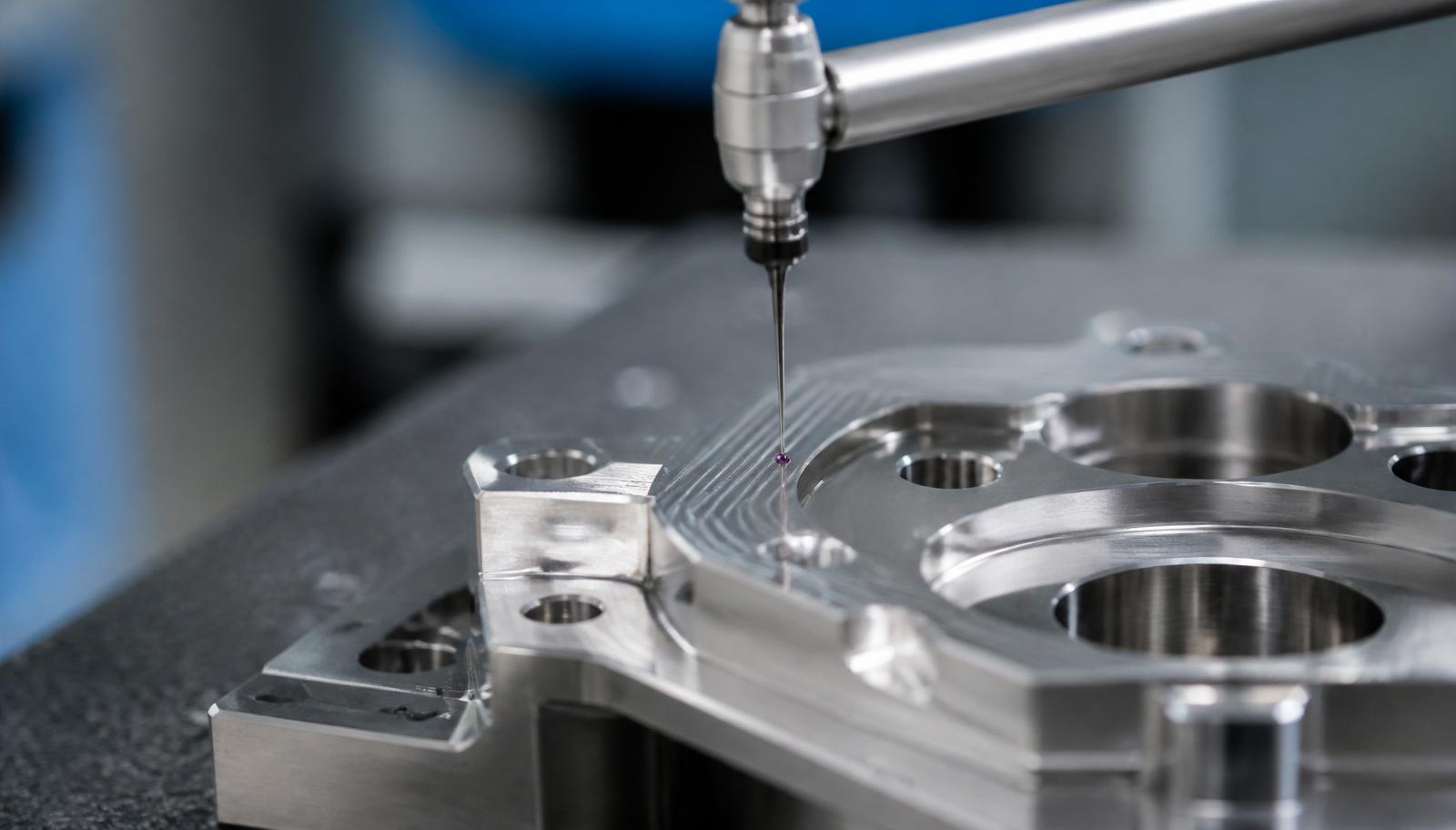
- Cross-referenced with CMM measurement on our Haas HMM 430 (milled parts) and Chien Wei CWB-450-CNC (turned parts) for form/waviness separation — see our CMM inspection capabilities post for the full metrology chain.
- PPAP/ISIR-compatible reports — every finish callout appears on its own row with measurement result, instrument S/N, and pass/fail.
- AS9102 Form 3 characteristic accountability — surface texture callouts are balloon-numbered and reported alongside dimensional characteristics. See our AS9102 first article inspection checklist.
- Traceability to NIST via calibrated roughness comparator specimens and annual instrument calibration.
7-Point Buyer Checklist: Specifying Surface Finish on Your Drawing
- Set a general note baseline. Example: "Unless otherwise stated, all machined surfaces Ra 3.2 µm (125 µin) max." This one line eliminates most RFQ back-and-forth on non-critical features.
- Call out tighter Ra only on functional surfaces. Every Ra callout below the general note adds cost. Justify each one against a sealing, sliding, fatigue, or cosmetic function.
- For seals and hydraulic surfaces, specify BOTH Ra and Rz. Ra alone will let a peak-heavy surface pass inspection and fail in the field.
- Specify lay direction for O-ring seats and dynamic seals. Use the ASME Y14.36 symbols (=, ⊥, X, M, C, R). Circumferential lay (C) is the default for round seal grooves.
- Reference the standard. "Per ISO 21920-2:2021" or "Per ASME B46.1-2019" on the drawing removes ambiguity about filter, cutoff, and evaluation length.
- Flag measurement certification in the RFQ. A signed surface finish report per feature adds inspection time — note it up front so the quote reflects it.
- Avoid over-specifying Ra < 0.8 µm without functional justification. Every step tighter than N6 typically doubles the finishing cost and adds a secondary process (grinding, honing, superfinishing).
Common Surface Finish Mistakes That Kill Aerospace RFQs
- No surface finish callout at all. The drawing defaults to "as-machined," which every shop interprets differently. Ambiguity becomes an NCR after the first shipment.
- Ra only on a seal. A dynamic seal that requires Rz control will pass Ra and leak in service.
- Wrong standard cited. A 2024 drawing that cites ISO 4287 forces the shop to guess whether the customer wants old-Rz or new-Rz. Cite ISO 21920-2 explicitly.
- No lay specification on a rotary seal. Axial lay on a rotating O-ring groove is a certified leak path.
- Ra < 0.4 µm on a non-critical surface. Doubles the machining cost, adds a secondary process, and rarely adds any function.
Frequently Asked Questions
What is the difference between Ra and Rz?
Ra is the arithmetic mean roughness — the average absolute deviation of the profile from its mean line over the evaluation length. Rz is the maximum peak-to-valley height within the evaluation length under ISO 21920-2:2021. Ra summarizes overall smoothness; Rz captures the worst single feature. For sealing, sliding, or fatigue-critical surfaces, always specify both.
What Ra value do I need for an aerospace sealing surface?
Static aerospace seals typically call out Ra 0.4–0.8 µm (16–32 µin) with a paired Rz limit. Dynamic seals and hydraulic surfaces are commonly Ra 0.2–0.4 µm with lay direction specified. Prime-specific process specs (Boeing D6-56000, GE P1TF14) can override these defaults — the drawing must be read against the referenced spec.
Do I need to specify surface finish on every drawing?
Yes. A single general note ("Unless otherwise stated, all machined surfaces Ra 3.2 µm max, per ISO 21920-2") on the drawing title block covers non-critical surfaces and eliminates most RFQ back-and-forth. Then add explicit callouts only on functional surfaces.
What's the difference between ISO 4287 and ISO 21920-2?
ISO 21920-2:2021 supersedes ISO 4287. The measurement physics did not change, but Rz is now the maximum peak-to-valley across the evaluation length (previously averaged across sampling lengths), most parameters are defined on the evaluation length rather than the sampling length, and Setting Classes Sc1–Sc5 standardize filter and section-length defaults. Aerospace primes are updating drawings — always confirm which standard the drawing invokes.
Can Olympus provide a surface finish certification with each shipment?
Yes. Surface texture callouts are reported on AS9102 Form 3 alongside dimensional characteristics, or on a standalone surface finish report per feature. Every measurement is captured with instrument S/N, cutoff length, evaluation length, and measurement direction relative to lay. Note the certification requirement in the RFQ so the quote reflects the added inspection time.
How much does a tighter surface finish add to CNC cost?
As a rule of thumb, each ISO grade step below N6 (Ra 0.8 µm) roughly doubles the finishing cost for that feature — because it typically forces a secondary process (grinding, honing, lapping, or superfinishing) beyond standard CNC. Ra 3.2 µm to Ra 1.6 µm is often free on the same tool path; Ra 0.8 µm to Ra 0.4 µm rarely is.
Need certified surface-finish reports on your aerospace or defense parts?
Olympus Machining provides Ra/Rz measurement per ISO 21920-2 and ASME B46.1-2019 alongside AS9102 Form 3 characteristic accountability on every shipment for Aerospace & Defense programs.
Get a quote AS9102 first article inspection checklist
Related Articles
Related Capabilities from Olympus Machining
Precision CNC Machining
Hanover, PA precision CNC shop for tight-tolerance aerospace and defense parts.
CNC Milling Services
Multi-axis precision milling for complex geometries and tight tolerances.
CNC Turning Services
Precision lathe machining for shafts, bushings, and cylindrical components.
Delrin (Acetal/POM) Machining Guide
Delrin/POM CNC machining guide — tolerances, applications, and finishing.
Inconel CNC Machining Guide
Inconel 718 and 625 machining strategies for aerospace superalloys.
ITAR CNC Machining (Mid-Atlantic Aerospace)
ITAR-registered aerospace CNC machining serving the Mid-Atlantic region.
AS9102 First Article Inspection
AS9102 Rev C FAI services with Forms 1, 2, and 3 documentation.
Submit Your Project for Review
Contact Olympus Machining to discuss your CNC machining requirements.