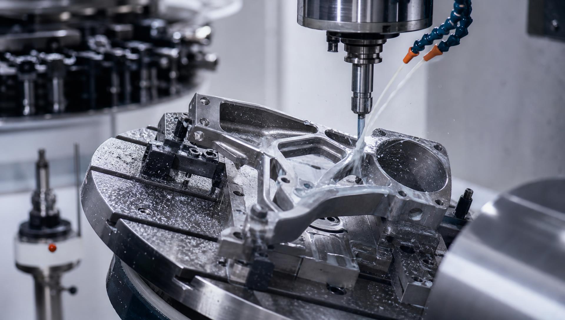
5-Axis CNC Milling for Aerospace Complex Geometries: When You Need It, When You Don't, and What to Look For in a Supplier
Precision CNC Machining • 5-Axis Milling • Aerospace & Defense
Not every aerospace part needs 5-axis machining — but the parts that do can’t be made any other way without stackup errors, extra fixtures, or scrap.
Hanover, PA — Olympus Machining LLC · ITAR registered · CAGE 9V9P0 · CMMC Level 1 · AS9100D In Progress.
Author: Olympus Machining · Reading time: ~9 min
At a Glance
- Roughly 70% of complex aerospace parts can be run in 3+2 positional 5-axis; only about 20% need full simultaneous motion
- 5-axis is cost-positive once the 3-axis approach needs 3 or more setups
- Every re-fixture adds ±0.0005″–0.001″ of stackup; four setups can reach ±0.004″
- Spindle-mounted probing separates a production 5-axis shop from a “5-axis capable” one
- Specifying 5-axis on a prismatic part is a pure cost penalty with no tolerance benefit
- 7-point buyer checklist and 6-question FAQ at the bottom of this post
Not every aerospace part needs 5-axis machining — but the parts that do can’t be made any other way without stackup errors, extra fixtures, or scrap. That distinction is the whole decision. A turbine airfoil, an impeller, or a titanium bracket with features on five non-orthogonal faces has geometry that a vertical spindle simply cannot reach in one orientation, and every additional orientation you add costs money and accuracy.
5-axis is not universally better; it is the right tool for a specific class of parts. This post explains when to require 5-axis on your RFQ, when it is a waste of program budget, and what to verify in a supplier’s 5-axis capability before you commit a part number to their shop.
3-Axis vs 3+2 vs Full 5-Axis: What Actually Changes at the Machine
3-axis machining uses X, Y, and Z linear motion only. The tool stays vertical and the part stays fixed in one orientation. It is entirely suitable for parts whose features are all accessible from one direction, or for parts that can be re-fixtured face by face without violating the tolerance scheme.
3+2 machining — also called positional or indexed 5-axis — adds A and C (or B) rotary axes, but those axes lock during the cut. The part is repositioned to a compound angle, clamped, and then machined in conventional 3-axis mode. It is faster than 3-axis because it eliminates setups, and simpler than full 5-axis because the CAM toolpaths are standard 3-axis strategies at a rotated work offset. For most aerospace brackets and housings, 3+2 is the sweet spot.
Full simultaneous 5-axis moves all five axes during the cut. It is required when the tool axis has to change continuously to stay normal to a curved surface — turbine airfoils, impeller blades, blended fillets between compound surfaces. CAM programming is significantly more complex, collision avoidance is non-trivial, and post-processor validation matters. The Haas 5-axis VMC line and the SME 5-axis primer both cover the kinematic distinction in detail.
A rule of thumb drawn from real aerospace jobs: roughly 70% of complex aerospace parts can be produced in 3+2 positional 5-axis, about 20% genuinely require full simultaneous motion, and the remaining 10% could have been done in 3-axis with better design for manufacturability.
When 5-Axis Is Required (Non-Negotiable)
- Undercuts and negative-draft features that cannot be reached from a single tool axis
- Compound-angle features — angled hole patterns oriented on multiple planes, angled seal faces, canted bosses
- Surfaces with continuous curvature: turbine airfoils, impellers, blended fillets on structural brackets
- Parts where tolerance stackup across multiple 3-axis setups exceeds the drawing spec — typically any feature-to-feature callout tighter than ±0.001″ across faces (see aerospace machining tolerances explained)
- Family-of-features parts that would need five or more 3-axis setups — a single-setup 5-axis operation eliminates fixture-induced stackup entirely
- Part families where lot size multiplied by setup cost exceeds the machine-rate delta between 3-axis and 5-axis
When 5-Axis Is a Waste of Money
- Prismatic parts — brackets, plates, and housings with orthogonal features only
- Parts with every feature accessible from one or two sides
- Simple turned parts with milled flats, where turn-mill is usually a better answer than 5-axis milling (see the milling vs. turning decision guide)
- Small parts where fixture setup time dominates cycle time — a 3-axis machine with dedicated soft jaws is often faster door to door
- Low-volume prototypes where 5-axis CAM programming hours exceed the cycle-time savings across the whole lot
Cost Delta: The Real 5-Axis Premium
| Machining Approach | Typical Shop Rate | Setup Count for Complex Part | Cycle Time Multiplier | Tolerance Stackup Risk |
|---|---|---|---|---|
| 3-axis, multiple setups | $75–95/hr | 4–6 setups | 1.0× (baseline) | High (fixture stack) |
| 3-axis with dedicated fixture | $75–95/hr | 2–3 setups | 0.8× | Moderate |
| 3+2 positional 5-axis | $110–140/hr | 1–2 setups | 0.6× | Low |
| Full simultaneous 5-axis | $130–170/hr | 1 setup | 0.5–0.7× | Minimal |
The 5-axis “premium” evaporates once you factor in eliminated setups, reduced fixturing, and tighter tolerance capability. For complex parts, 5-axis is usually the lower total-cost approach — the higher hourly rate is offset by fewer setups and less scrap.
The Setup Reduction Math That Justifies 5-Axis
Every additional setup adds four costs: fixture design and build, operator setup time (typically 30–90 minutes), tolerance stackup between datums, and the risk of scrapping a part if any single setup drifts.
Take a titanium bracket with features on five faces. Run 3-axis, it needs five setups at roughly 60 minutes each — five hours of setup, four fixtures, and a realistic feature-to-feature stackup near ±0.002″. Run the same part 3+2, and it is one trunnion fixture, one 45-minute setup, and stackup around ±0.0005″. Even at $140/hr against $85/hr, the 5-axis route saves more than three hours per part and holds a tolerance the 3-axis route cannot reach at all.
The working rule: 5-axis is cost-positive when the 3-axis approach requires three or more setups. Below that threshold, a good 3-axis shop with dedicated workholding usually wins on price.
Tolerance Stackup: The Hidden Reason 5-Axis Wins
Every re-fixture introduces at minimum ±0.0005–0.001″ of positional error, even with precision workholding, ground locators, and careful datum transfer. Four setups can stack to ±0.002–0.004″ of feature-to-feature error before a single tool wears.
Aerospace bracket-to-bracket mating features routinely require ±0.001″ or tighter. That is effectively impossible with a four-setup 3-axis plan and straightforward with a one-setup 5-axis plan. The same logic governs the strategies described in holding 0.0001″ tolerances and machining strategies for 0.0005″ tolerance.
On-machine probing reduces the residual further by auto-correcting work offsets between operations. Machine accuracy itself should be evaluated against published test codes — ISO 230-1 for geometric accuracy and ASME B5.54 for machining center performance evaluation.
5-Axis Probing: What Separates a Real 5-Axis Shop from a “5-Axis Capable” Shop
- A spindle-mounted touch probe such as the Renishaw OMP600 or Blum TC50 for on-machine part verification
- Automatic alignment of the part to the CAM origin, eliminating manual edge-finding on complex trunnion fixtures
- In-cycle inspection between operations, catching an out-of-tolerance feature before the next cut commits scrap
- Tool-length and tool-breakage detection, which is a hard prerequisite for lights-out 5-axis running
- Probing is upstream QC; CMM inspection remains the final dimensional authority
Materials That Practically Require 5-Axis for Aerospace
- Titanium Ti-6Al-4V structural brackets and gearbox housings — thin walls, compound geometry, tight tolerances (see titanium CNC machining for aerospace)
- Inconel 718 turbine components — heat-resistant alloy with continuously curved surfaces (see the Inconel machining guide)
- 17-4 PH stainless landing gear fittings — compound angles at high strength
- 7075-T6 aluminum structural components — thin walls, deep pockets, compound-angle features
- Delrin/POM fixtures and prototype tooling can usually stay 3-axis — the material does not demand 5-axis (see the Delrin machining guide)
How Olympus Machining Delivers 5-Axis Aerospace Work
- Haas HMM 430 5-axis vertical machining center with trunnion — both 3+2 positional and full simultaneous capability
- Renishaw spindle-mounted probing for on-machine verification and closed-loop offset correction
- Chien Wei CWB-450-CNC turn-mill for cylindrical parts with milled features, a 5-axis-adjacent capability that often beats 5-axis on cost
- A 5-axis DFM review included on every RFQ where 5-axis is a candidate
- AS9100D-aligned first article inspection on 5-axis parts (see the AS9102 FAI checklist)
- CMM verification of 5-axis output on our Haas HMM 430 and Chien Wei CWB-450-CNC
- Full traceability of 5-axis operations, tool life, and probe results per AS9100D §8.5.2
- ITAR-registered and CMMC Level 1 compliant for defense 5-axis work, with a documented path from prototype to production volume
7-Point Buyer Checklist: Deciding If Your Part Needs 5-Axis
- Count the faces carrying features. Three or more non-orthogonal faces means 5-axis is likely required.
- Check for undercuts, compound angles, or continuously curved surfaces. These are 5-axis-only features.
- Sum feature-to-feature tolerances across faces. If any pair is ±0.001″ or tighter, single-setup 5-axis is the safer plan.
- Ask the supplier how they would quote it. “3-axis, 3+2, or full simultaneous — and why?” Real 5-axis shops articulate the choice.
- Verify spindle-mounted probing on the 5-axis machine. This separates “capable” from production-ready.
- Ask for their AS9102 FAI process on 5-axis parts. Stackup shows up in Form 3 characteristic accountability.
- Request a 5-axis DFM review. Good shops will tell you when 3-axis is actually cheaper for your part.
Common 5-Axis Mistakes That Blow Aerospace Budgets
- Specifying “5-axis required” on a prismatic part that is cheaper and just as accurate in 3-axis
- Choosing a “5-axis capable” shop with no probing — their stackup can be worse than a good 3-axis shop with dedicated fixtures
- Writing tolerances that force 5-axis when a DFM revision would allow 3-axis at roughly 40% lower cost
- Assuming full simultaneous 5-axis when 3+2 positional would work — paying the higher machine rate for no benefit
- Not requiring on-machine probing, so the first article passes and production quietly drifts (a clean STEP file and clear finish callouts help catch this early)
FAQ
What is the difference between 3+2 positional 5-axis and full simultaneous 5-axis machining?
In 3+2 positional machining the two rotary axes index the part to a compound angle and then lock, so the cut itself is a conventional 3-axis toolpath at a rotated work offset. In full simultaneous 5-axis, all five axes move during the cut so the tool axis can stay normal to a continuously changing surface. 3+2 covers most aerospace brackets and housings; simultaneous motion is reserved for airfoils, impellers, and blended compound surfaces.
When does aerospace CNC machining actually require 5-axis, and when is 3-axis enough?
5-axis is required when features are inaccessible from a single tool axis, when surfaces are continuously curved, or when feature-to-feature tolerances across multiple faces are tighter than about ±0.001 inch. 3-axis is enough for prismatic parts with orthogonal features accessible from one or two sides, and it is usually cheaper when fewer than three setups are needed.
Is 5-axis machining always more expensive than 3-axis?
No. The hourly rate is higher — typically $110–170 per hour versus $75–95 — but 5-axis eliminates setups, fixtures, and scrap risk. Once a part needs three or more 3-axis setups, the 5-axis approach is usually the lower total cost, and it delivers tolerances the multi-setup approach cannot hold.
Does Olympus Machining offer 5-axis CNC milling for aerospace parts?
Yes. Olympus runs a Haas HMM 430 5-axis vertical machining center with a trunnion table, supporting both 3+2 positional and full simultaneous 5-axis work, with Renishaw spindle-mounted probing, CMM verification, AS9100D-aligned FAI, and ITAR-registered, CMMC Level 1 handling for defense programs.
What is on-machine probing, and why does it matter for 5-axis aerospace parts?
On-machine probing uses a spindle-mounted touch probe to locate the part, align it to the CAM origin, and measure features between operations without unclamping. On 5-axis work it removes manual edge-finding on complex fixtures, corrects rotary offsets automatically, and catches out-of-tolerance features before the next cut — which is what keeps production from drifting after a passing first article.
Can I mix 3-axis and 5-axis operations on the same aerospace part?
Yes, and it is often the cheapest plan. A common approach is roughing and simple facing on a 3-axis machine, then a single 5-axis finishing setup for the compound-angle and curved features that carry the tight tolerances. The tradeoff is one additional datum transfer, so the mixed plan makes sense when the critical features are grouped into the 5-axis operation.
Not sure whether your part needs 5-axis?
Send a STEP file and Olympus Machining will tell you whether we would quote it 3-axis, 3+2, or full simultaneous 5-axis — and why — alongside precision CNC machining, CNC milling, CNC turning, and CMM-verified inspection for Aerospace & Defense programs.
Related Articles
Related Capabilities from Olympus Machining
Precision CNC Machining
Hanover, PA precision CNC shop for tight-tolerance aerospace and defense parts.
CNC Milling Services
Multi-axis precision milling for complex geometries and tight tolerances.
CNC Turning Services
Precision lathe machining for shafts, bushings, and cylindrical components.
Surface Finish Requirements
Ra, Rz, and what aerospace buyers actually need to specify.
Aerospace Machining Tolerances Explained
How aerospace tolerance callouts drive process selection and cost.
Holding 0.0001" Tolerances
Shop-floor strategies for tenth-thousandth aerospace tolerance work.
Machining Strategies for 0.0005" Tolerance
Process planning and workholding for half-thou tolerance callouts.
CMM Inspection Capabilities & Reporting
How CMM reporting proves the tolerances your drawing calls out.
Traceability in Aerospace & Defense CNC
Material certs, lot control, and AS9100D chain of custody.
Scaling Prototype to High-Volume Production
DFM handoff, tooling investment, and process qualification for OEM programs.
AS9102 First Article Inspection Checklist
Forms 1, 2, and 3 characteristic accountability on first articles.
STEP Files for CNC Machining Quotes
How to export CAD data that quotes accurately the first time.
Inconel CNC Machining Guide
When Inconel 718 is functionally required — and what it costs to machine.
Delrin (Acetal/POM) Machining Guide
Low-cost precision plastic components for non-metallic applications.
ITAR CNC Machining, Mid-Atlantic
ITAR-registered machining for Mid-Atlantic aerospace and defense programs.
Submit Your Project for Review
Contact Olympus Machining to discuss your CNC machining requirements.