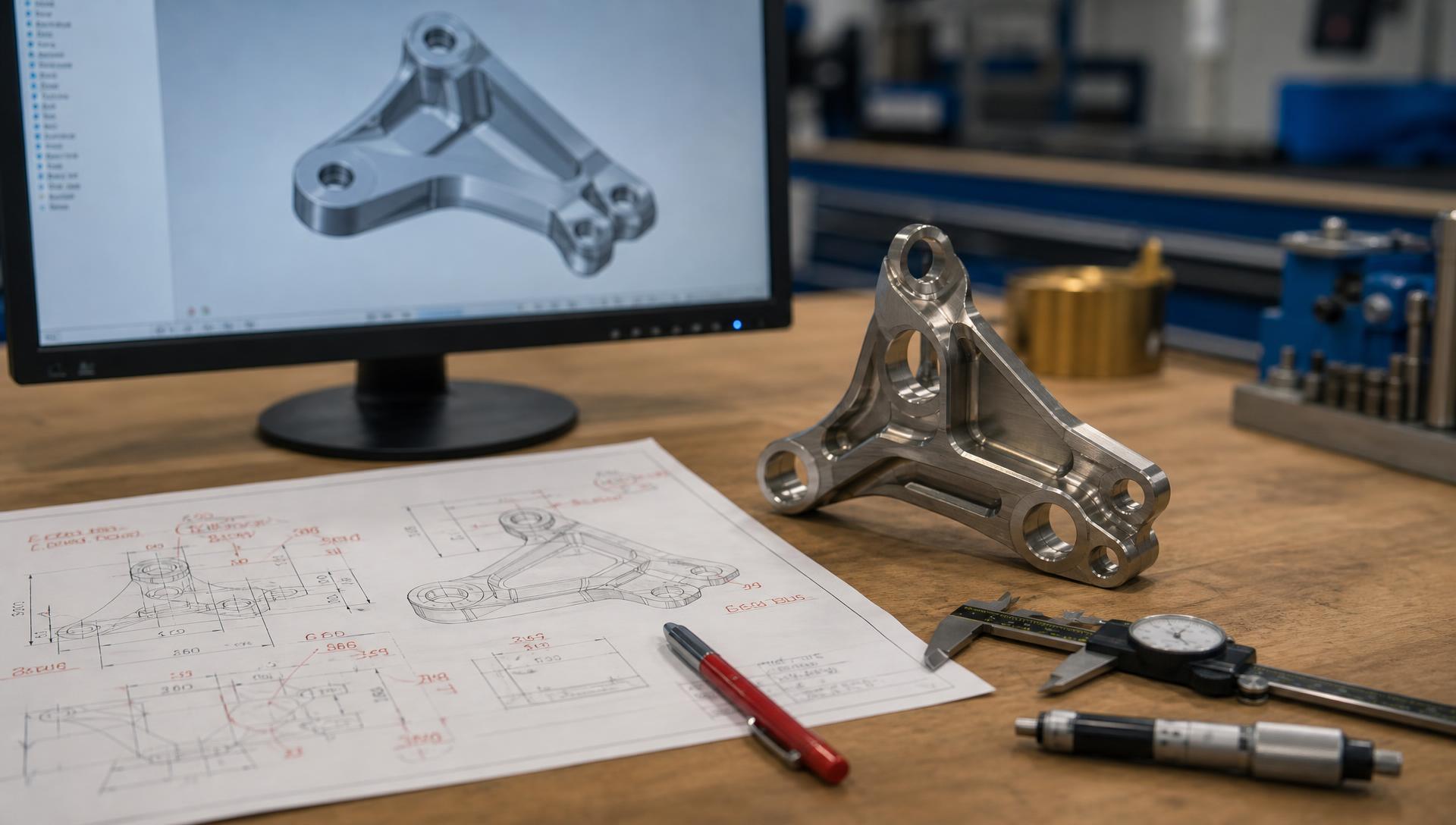
Design for Manufacturability (DFM) for Aerospace CNC Parts: How to Reduce Cost and Lead Time Before You Cut Metal
Precision CNC Machining • Design for Manufacturability • Aerospace & Defense
Eighty percent of your aerospace CNC part’s final cost is locked in during the design phase, not the quoting phase.
Hanover, PA — Olympus Machining LLC · ITAR registered · CAGE 9V9P0 · CMMC Level 1 · AS9100D In Progress.
Author: Olympus Machining · Reading time: ~9 min
At a Glance
- DFM is the cheapest cost lever an aerospace engineer has — it costs nothing but review time
- Internal corner radii, wall thickness, and blanket tight tolerances drive most avoidable cost
- A blanket ±0.0005″ note can raise unit price 50% with zero functional benefit
- Material over-specification (Inconel where Ti-6Al-4V works) is a 100–300% cost error
- Olympus provides a free DFM review on every RFQ with a STEP file, 24–48 hour turnaround
- 7-point buyer checklist and 6-question FAQ at the bottom of this post
Eighty percent of your aerospace CNC part’s final cost is locked in during the design phase, not the quoting phase. By the time a STEP file reaches a machine shop, the corner radii, wall thicknesses, tolerance blocks, datum scheme, and alloy have already decided how many setups the part needs, which cutters can reach the features, and how much inspection the drawing demands. The quote is arithmetic on decisions that were made weeks earlier in CAD.
That makes Design for Manufacturability the fastest and cheapest lever an aerospace or defense engineer has to reduce cost and lead time — and it costs nothing to pull. This post covers what a design engineer needs to know before sending a STEP file out for quote, the specific feature rules that govern CNC cost, and how Olympus Machining runs a formal DFM review on every RFQ we receive.
What Design for Manufacturability Actually Means
Design for Manufacturability is the practice of designing parts so they can be manufactured efficiently, at the required quality, and at the lowest cost — without compromising function. That last clause is the whole discipline. DFM is not value engineering, and it is not asking an engineer to loosen a tolerance that a bearing fit actually needs. It is the systematic removal of cost that buys nothing.
Every DFM decision balances three variables: cost, lead time, and quality. Loosening a non-functional tolerance reduces cost and lead time with no quality impact. Adding a corner radius reduces cost and lead time and typically improves quality by eliminating a secondary EDM operation. Tightening a tolerance on a functional mating surface increases cost and lead time and is often the right call. The goal is to spend the budget where it does structural work.
Aerospace and defense engineers under-prioritize DFM for a rational reason: safety-critical design bias. When a failure mode is loss of aircraft, “tighter is safer” is a defensible instinct. But a blanket ±0.0005″ note on a bracket with three functional surfaces does not make the bracket safer — it makes 40 non-functional dimensions expensive to produce and expensive to inspect, and it dilutes inspection attention away from the features that actually matter. Rigor and over-specification are not the same thing.
The economics are well documented. Roughly 70% of a part’s total lifecycle cost is committed during design, while machining itself typically accounts for a small fraction of the committed total. NIST research on design-phase cost commitment and studies published by aerospace primes both land in the same range, and the SME overview of design for manufacturability reaches the same conclusion from a shop-floor perspective. Cost is decided in CAD and merely observed on the quote.
The 12 Most Common DFM Mistakes That Add 30% to an Aerospace CNC Quote
These are the twelve callouts our estimators flag most often on aerospace and defense RFQs, with the typical cost impact and the alternative that preserves function.
| # | Design Mistake | Cost Impact | Better Approach |
|---|---|---|---|
| 1 | Sharp internal corners (0° radius) | +25% cycle time (EDM required) | Use a corner radius ≥ 1/3 pocket depth |
| 2 | Wall thickness < 0.020″ on aluminum, < 0.030″ on titanium | +40% (chatter, deflection) | Match wall to material stiffness rules |
| 3 | Deep pockets with high depth-to-width ratio (>4:1) | +30% (long tools, low feeds) | Break into shallower features or open access |
| 4 | Uniform tight tolerances (±0.0005″) across all features | +50% (100% CMM required) | Callout tight tolerances only on functional surfaces |
| 5 | Surface finish Ra ≤ 32 µin on non-critical faces | +20% (grinding/polishing) | Ra 125 µin as-machined default (see our Surface Finish guide) |
| 6 | Threads to bottom of blind hole | +15% (specialty taps, low tool life) | Leave 1.5× thread pitch clearance |
| 7 | Non-standard hole sizes | +10% (custom tooling) | Use standard drill/reamer sizes |
| 8 | Multi-axis features that require 5-axis when 3-axis would work | +40% (higher machine rate) | Split part into 3-axis-friendly setups |
| 9 | Excessive datum stacks (>3 primary datums) | +20% (fixture complexity) | Simplify GD&T scheme |
| 10 | Inconel or Hastelloy when Ti-6Al-4V or 17-4 PH would meet function | +100–300% (material + tool cost) | Confirm alloy is functionally required |
| 11 | Countersinks/counterbores not aligned to standard fastener sizes | +15% (custom tooling) | Match ANSI/ASME B18 fastener standards |
| 12 | No draft, deep engraved characters, or micro-features < 0.010″ | +25% (specialty engraving) | Use laser marking or standard character libraries |
Feature-by-Feature DFM Rules for CNC (Aerospace Baseline)
Corner Radii
Internal corners should carry a minimum radius equal to 1/3 of the pocket depth; deeper pockets need larger radii so the end mill has enough stiffness to avoid deflection and breakage. External corners need no radius for cost reasons, and where an edge break is required, a chamfer is cheaper than a radius. As a rule of thumb, a 0.125″ end mill cuts a 0.0625″ internal radius — anything tighter forces a smaller cutter, slower feeds, and more passes.
Wall Thickness
Minimum stable wall thickness is a material property, not a universal number. Aluminum 6061-T6 and 7075-T6 machine reliably down to 0.030″, and 0.020″ is achievable with careful fixturing that adds cost. Ti-6Al-4V wants 0.040″ minimum — thin titanium walls chatter and tool deflection is a real problem. Stainless 17-4 PH and 304 hold at 0.030″. Inconel 718 needs 0.050″, because a wall that vibrates during the cut work-hardens and destroys the next pass.
Hole and Thread Design
Drilled depth of 4× diameter is comfortable; up to 8× is possible with peck drilling at the cost of cycle time. Tapped blind holes should leave 1.5× thread pitch of clearance at the bottom so the tap does not bottom out. Prefer standard drill sizes — numbered #1–#80, letter drills A–Z, and fractional 1/64″ increments — because a custom hole diameter means custom tooling, custom lead time, and a spare-tool problem on every reorder.
Tolerance Strategy
A default drawing note of “unless otherwise stated, ±0.005″” is the correct aerospace baseline. Anything tighter as a general note is expensive over-specification. Reserve ±0.0005″ for functional and mating surfaces — see our field guides on aerospace machining tolerances, holding tenth-thousandth tolerances, and machining strategies for 0.0005″ work. Keep the datum scheme to three primary datums, aligned with the planes the fixture will actually locate on, per ASME Y14.5-2018. For surface texture, Ra 125 µin (3.2 µm) as-machined is the baseline, and Ra 32 µin (0.8 µm) or better belongs only where a seal, bearing, or fatigue requirement demands it.
Material Selection
Aluminum is the cheapest alloy family to machine and the right default for weight-critical, non-load-bearing structure. 17-4 PH stainless covers corrosion plus strength at moderate temperature. Ti-6Al-4V earns its cost on structures that need high strength-to-weight. Inconel 718 should be specified only where service temperature above roughly 1200°F or an aggressive corrosion environment demands it — it runs 3–5× the cost of titanium once tool wear is counted. For non-metallic, lightweight precision components, Delrin/POM is often the lowest-cost answer. The ASM International materials selection resources are the standard reference for justifying the substitution.
Tool Access and Setup Count
Design so that as many features as possible can be machined from a single setup. Every additional setup adds fixturing, handling, and — more importantly — tolerance stack-up between features referenced across setups. Avoid features on five or more faces when 3-axis milling can do the job, and keep tool length-to-diameter ratios under 5:1 wherever the geometry allows.
How Olympus Machining Runs a Formal DFM Review
Olympus provides a free DFM review on every RFQ where a STEP file is supplied — see our guide to STEP files for CNC machining quotes for export settings. STEP AP242 (ISO 10303-242) is preferred because it carries model-based definition: datums, tolerances, and surface finish travel with the geometry instead of living on a separate PDF.
Turnaround is 24–48 hours for standard-complexity parts. Deliverables are an annotated PDF markup, a cost-impact estimate per callout, and alternative-approach recommendations. Every comment is categorized in one of three buckets: (1) will not affect function, save cost; (2) may affect function, discuss with engineering; (3) required by function, no change recommended. That third category matters — a DFM review that never says “leave it alone” is a cost-cutting exercise, not an engineering one.
Any DFM-driven change the customer accepts runs through AS9100D-aligned change control. Modified features are verified on our Haas HMM 430 and Chien Wei CWB-450-CNC CMMs before production release — see our CMM inspection capabilities and reporting standards post — and every DFM revision is carried through the FAI package under AS9102 Rev C with full traceability from drawing revision to shipped lot.
7-Point Buyer Checklist: Running a DFM Review Before RFQ
- Export a clean STEP (AP242) file. Datums, tolerances, and surface finish embedded as MBD — or attach a fully dimensioned PDF drawing.
- Review your general note tolerance. Is ±0.005″ enough as a baseline? It usually is.
- Callout tight tolerances only on functional surfaces. Mating faces, bearing bores, seal grooves — not every dimension.
- Verify internal corner radii are ≥ 1/3 pocket depth. CAD auto-generates sharp corners; catch them before RFQ.
- Check wall thicknesses against material minimums. Aluminum 0.030″, titanium 0.040″, Inconel 0.050″.
- Confirm the material is functionally required. Inconel versus titanium is often a >$500/part difference.
- Ask your CNC supplier for a formal DFM review before issuing the RFQ. Most quality shops, Olympus included, provide it free.
Common DFM Failures That Blow the Program Budget
- Uniform ±0.0005″ tolerance on every dimension because “it’s aerospace” — a 3× cost increase for zero functional benefit.
- Inconel specified because “high temperature” — max service temp turns out to be 400°F, and Ti-6Al-4V would have worked at a quarter of the cost.
- Sharp internal corners because CAD auto-generated them — forces wire or sinker EDM as a secondary operation with its own lead time.
- Micro-features under 0.010″ engraved on a part that will be painted — useless and expensive at the same time.
- No DFM review before RFQ, so six rounds of drawing revisions during prototyping — a four-week schedule slip that no one budgeted.
FAQ
What is Design for Manufacturability (DFM) in aerospace CNC machining?
DFM is the practice of designing parts so they can be manufactured efficiently, at the required quality, and at the lowest cost without compromising function. In aerospace CNC work it focuses on corner radii, wall thickness, tolerance and datum strategy, tool access, setup count, and alloy selection — the design decisions that commit the majority of the part’s manufacturing cost before any material is cut.
Does Olympus Machining provide free DFM reviews?
Yes. Olympus provides a free DFM review on every RFQ that includes a STEP file, with 24–48 hour turnaround on standard-complexity parts. Deliverables are an annotated PDF markup, a cost-impact estimate for each callout, and alternative-approach recommendations categorized by whether they affect function.
What file format should I send for a DFM review?
STEP AP242 (ISO 10303-242) is preferred because it carries model-based definition — datums, tolerances, and surface finish travel with the geometry. STEP AP203/AP214 plus a fully dimensioned PDF drawing also works. Native CAD files, IGES, and Parasolid can be accepted, but MBD-capable STEP produces the most complete review.
Will DFM feedback require changes to my drawing?
Not necessarily. Feedback is categorized as: will not affect function and saves cost; may affect function and should be discussed with engineering; or required by function with no change recommended. The customer decides what to accept. Any change that is accepted runs through AS9100D-aligned change control and a drawing revision before production release.
How much can a good DFM review actually save on an aerospace CNC part?
Typical savings run 15–30% on unit price when common issues are present, and considerably more when material is over-specified — substituting Ti-6Al-4V for Inconel 718 where service conditions allow can cut material and tooling cost by 100–300%. Lead-time savings are often larger in program terms, because eliminating secondary EDM operations and drawing revision cycles removes weeks from the schedule.
Can DFM be done on parts already in production, or only during design?
DFM can be applied to parts already in production, and it frequently pays off on long-running programs — but the change control burden is higher. A part in production has an approved FAI, a qualified process, and often a frozen configuration, so any DFM change requires a drawing revision, re-qualification of affected characteristics, and in many cases a partial FAI (PFAI). The leverage is highest during design; the savings are still real at re-quote or annual cost-down review.
Want a free DFM review on your next aerospace part?
Send a STEP file and Olympus Machining will return an annotated markup with cost-impact estimates in 24–48 hours — precision CNC machining, CNC turning, and CMM-verified inspection for Aerospace & Defense programs.
Get a quote How to export a STEP file
Related Articles
Related Capabilities from Olympus Machining
Precision CNC Machining
Hanover, PA precision CNC shop for tight-tolerance aerospace and defense parts.
CNC Milling Services
Multi-axis precision milling for complex geometries and tight tolerances.
CNC Turning Services
Precision lathe machining for shafts, bushings, and cylindrical components.
Holding 0.0001" Tolerances
Shop-floor strategies for tenth-thousandth aerospace tolerance work.
Machining Strategies for 0.0005" Tolerance
Process planning and workholding for half-thou tolerance callouts.
CMM Inspection Capabilities & Reporting
How CMM reporting proves the tolerances your drawing calls out.
Traceability in Aerospace & Defense CNC
Material certs, lot control, and AS9100D chain of custody.
Scaling Prototype to High-Volume Production
DFM handoff, tooling investment, and process qualification for OEM programs.
CNC Milling vs. Turning for Prototypes & Aerospace Parts
Choosing mill vs lathe for metal prototypes and aerospace geometries.
Titanium CNC Machining
Ti-6Al-4V machining practice for aerospace structures.
Inconel CNC Machining Guide
When Inconel 718 is functionally required — and what it costs to machine.
Delrin (Acetal/POM) Machining Guide
Low-cost precision plastic components for non-metallic applications.
ITAR CNC Machining, Mid-Atlantic
ITAR-registered machining for Mid-Atlantic aerospace and defense programs.
Submit Your Project for Review
Contact Olympus Machining to discuss your CNC machining requirements.