How Aerospace Parts Are Built: A CNC Machining Field Guide from Design to AS9102 Delivery
Aerospace Manufacturing • CNC Machining • Field Guide
How Aerospace Parts Are Built: A CNC Machining Field Guide from Design to AS9102 Delivery
A working overview of how flight-quality aerospace parts are actually built — from drawing release through material certification, programming, machining, inspection, and AS9102 delivery — written from a U.S.-based precision CNC shop located in Hanover, Pennsylvania that runs aerospace work daily.
TL;DR
- Aerospace parts are built through a controlled chain: drawing review, material traceability, programming, fixture design, machining, in-process inspection, AS9102 First Article Inspection, and documented delivery.
- The critical engineering decisions happen before the first chip: datum strategy, fixture rigidity, stress-relief planning, and tool path approach drive whether tight tolerances actually hold.
- Aluminum 7075-T6, Ti-6Al-4V, Inconel 718, and 15-5 PH stainless are the workhorse alloys; each demands different speeds, feeds, tooling, and coolant strategy.
- Documentation is part of the product. AS9102 Forms 1/2/3, material certs, and CMM reports travel with the parts — without them, the parts cannot be installed on a flight asset.
Step 1: Drawing release and design-for-manufacturability review
Every aerospace part starts as a controlled drawing — typically a 3D model plus a 2D drawing with full GD&T per ASME Y14.5. Before a quote is even firm, a qualified CNC shop runs a design-for-manufacturability (DFM) review: which datums drive the inspection plan, which features are the cost drivers, and which callouts (true position, profile of a surface, runout) require special process control.
Common DFM findings on aerospace parts include sharp internal corners that force smaller cutters and longer cycle times, deep pockets with high length-to-diameter ratios, thin walls under 0.040" that warp during machining, and stacked tolerance chains that mathematically can't hold once you account for fixture and gauge uncertainty. The DFM conversation is where a good shop earns its margin — and where program risk is removed before metal is cut.
Step 2: Material selection and traceability
Aerospace material is never a generic purchase. Every bar, plate, or billet must arrive with a certified mill test report (CMTR) tied to a heat or lot number, and that number follows the part through every operation. The most common aerospace alloys we machine include:
- Aluminum 7075-T6 — primary structural alloy for airframes, brackets, and machined fittings; high strength-to-weight, predictable machinability.
- Aluminum 6061-T6 — secondary structural and tooling alloy; easier to machine than 7075, better corrosion resistance.
- Ti-6Al-4V (Grade 5 Titanium) — high-temperature engine fittings, landing-gear components, fasteners; demands slow speeds, sharp tooling, flood coolant.
- Inconel 718 — hot-section engine hardware; work-hardens aggressively, requires rigid setups and ceramic or coated carbide tooling.
- 15-5 PH and 17-4 PH stainless — actuator components and structural fittings requiring corrosion resistance plus high strength after age hardening.
The certs are scanned into the job traveler at receiving and stay with the work order. If the customer requires DFARS-compliant specialty metals, the cert chain has to prove melt and pour origin in a qualifying country — a documentation requirement that has stopped more aerospace deliveries than any tolerance issue.
Step 3: Programming, fixturing, and process planning
CAM programming for aerospace work is rarely a one-pass affair. The programmer plans rough, semi-finish, and finish operations separately, choosing tools and stepovers that leave consistent stock for each pass. Critical surfaces are programmed with climb milling, low radial engagement, and finishing passes that take 0.005"–0.010" to control deflection and heat input.
Fixturing is where aerospace work either succeeds or fails. A 0.0005" feature on a thin-walled 7075 housing cannot be held with a standard vise — it needs a soft-jaw or vacuum fixture that supports the part without distorting it. For Ti-6Al-4V parts, fixtures are designed to evacuate chips and flood coolant directly into the cut zone, because heat is the enemy in titanium machining.
Stress-relief is built into the process plan. After rough machining a thick 7075 plate, the part often comes off the machine, gets stress-relieved, and is re-fixtured for finishing. Skipping that step is the number-one cause of parts that pass inspection on the floor and warp out of tolerance on the customer's gauge.
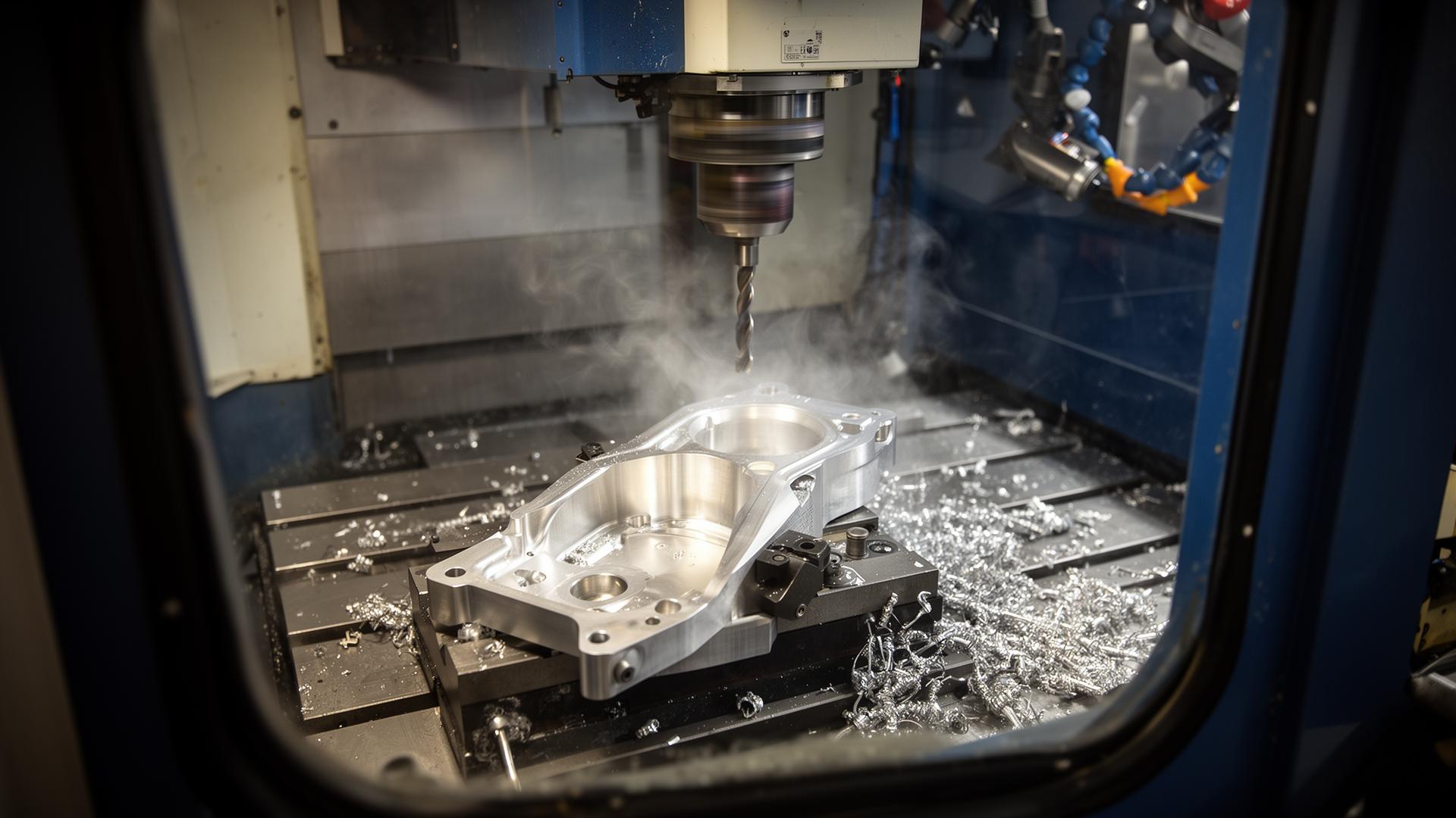
Step 4: Machining — milling, turning, and mill-turn
Most aerospace parts are produced on 3-, 4-, or 5-axis CNC milling centers, CNC turning centers, or mill-turn machines that combine both. The process choice follows the part geometry: rotational parts (bushings, shafts, fittings) go to turning; prismatic parts (brackets, ribs, manifolds) go to milling; hybrid parts go to mill-turn or a planned two-process sequence. We cover that decision in depth in our CNC milling vs. turning decision guide.
In-process inspection happens at planned breakpoints, not just at the end. On a 5-axis program for a structural fitting, the operator probes datum surfaces after roughing, after stress-relief and refixturing, and again before the finishing passes. On long-cycle Inconel parts, tool wear is monitored on a per-feature basis because a single dull insert can scrap a part with eight hours of machine time in it.
Step 5: Inspection — CMM, surface finish, and AS9102 FAI
Final inspection on aerospace work is performed on a coordinate measuring machine (CMM) against a balloon drawing — a print where every dimension is numbered and tied to a row in AS9102 Form 3. For first articles, every characteristic is measured and recorded. For production runs, sampling plans (often per AS9138 or customer-specified) determine which features are 100% inspected, which are sampled, and which are verified by process capability data.
Surface finish, geometric tolerances (flatness, perpendicularity, true position), and threaded-feature inspection are all part of the FAI package. For deeper detail on the CMM side of this, see our CMM inspection checklist for aerospace CNC parts and the AS9102 First Article Inspection capability page.
Step 6: Documentation, packaging, and delivery
An aerospace part is not deliverable until the paperwork is deliverable. A typical shipment includes the AS9102 Forms 1/2/3, material CMTRs, certificate of conformance, balloon drawing, CMM report, traceable serial numbers where required, and any special-process certs (heat treat, anodize, passivation, NDT). Parts are packaged in protective trays or VCI bags to prevent corrosion and surface damage in transit, and the documentation packet ships with the parts — physically and, increasingly, as a controlled digital package.
Compliance and information handling
Aerospace and defense work brings a second layer of requirements beyond the part itself. ITAR-controlled drawings must be handled only by U.S. persons inside a registered facility. CMMC Level 1 and FAR 52.204-21 require basic safeguarding of Federal Contract Information — access control, media protection, and audit trails on the engineering data, not just the parts. Olympus Machining is ITAR-registered and operates a CMMC Level 1 / FAR 52.204-21 aligned program; details are on the CMMC Level 1 compliance page and the credentials and capability statement.
Frequently asked questions
What tolerances are typical on aerospace CNC parts?
Most aerospace prints carry general tolerances of ±0.005" with critical features held to ±0.0005" or tighter. True position on bolt patterns is commonly 0.005"–0.010" diametrical. We cover the tightest end of that range in our guide to holding 0.0001" tolerances in aerospace CNC machining.
How long does an aerospace First Article Inspection take?
A complete AS9102 FAI on a moderate-complexity part typically adds 1–3 days to lead time for measurement, documentation, and review. Complex 5-axis parts with 200+ characteristics can take a week of CMM time alone.
Why is titanium harder to machine than aluminum?
Titanium has low thermal conductivity, so heat stays at the cutting edge instead of leaving in the chip. It also work-hardens. The result is shorter tool life, slower feeds, and a hard requirement for flood coolant and rigid setups.
What's the difference between a Form 1, Form 2, and Form 3 on an AS9102 FAI?
Form 1 identifies the part and the FAI. Form 2 documents the materials, processes, and special process certifications. Form 3 lists every drawing characteristic with the measured result. We explain the full structure in our AS9102 First Article Inspection checklist.
Do you handle ITAR-controlled aerospace drawings?
Yes. Olympus Machining is a U.S.-based, ITAR-registered precision CNC shop. ITAR-controlled technical data is restricted to U.S. persons and handled on segmented systems inside our Hanover, PA facility.
Explore Olympus Machining's CNC milling, CNC turning, materials capabilities, aerospace and defense industry page, AS9102 First Article Inspection, and prototype-to-production scaling.
Contact Olympus Machining
Olympus Machining LLC
639 Frederick St, Suite 1
Hanover, PA 17331
Phone: (717) 634-5094
Website: www.olympusmachining.com
Request a Quote: Submit a project
About Olympus Machining
Olympus Machining LLC is a precision CNC machining shop located in Hanover, Pennsylvania. As a dedicated CNC machining shop and reliable machining vendor, we provide CNC milling, CNC turning, and prototype-to-production services for OEMs and aerospace manufacturers nationwide. ITAR registered, CMMC Level 1, CAGE 9V9P0.
Related Articles
Related Capabilities from Olympus Machining
Aerospace & Defense Industry
AS9102-aligned, ITAR-registered aerospace and defense machining.
Titanium CNC Machining
Ti-6Al-4V and other titanium alloys for aerospace structural parts.
AS9102 First Article Inspection
Forms 1, 2, and 3 documentation for aerospace first articles.
Precision CNC Machining
Hanover, PA precision CNC shop for tight-tolerance aerospace parts.
Submit Your Project for Review
Contact Olympus Machining to discuss your CNC machining requirements.