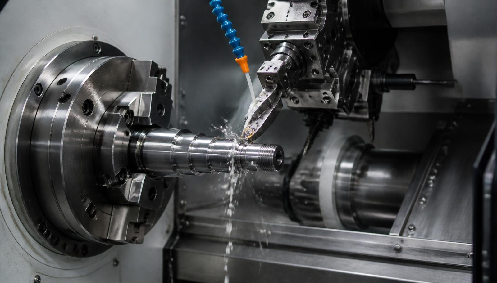
The Advantages of High-Precision CNC Turning for Cylindrical Components: Capabilities, Tolerances, and Multi-Axis Turn-Mill for Aerospace and Defense
Precision CNC Machining • CNC Turning • Aerospace & Defense
Getting a cylindrical part truly round is a spindle problem, not a programming problem — and that is why turning still owns the tightest concentricity work in aerospace and defense.
Hanover, PA — Olympus Machining LLC · ITAR registered · CAGE 9V9P0 · CMMC Level 1 · AS9100D In Progress.
Author: Olympus Machining · Reading time: ~9 min
At a Glance
- Turning defines the axis of rotation mechanically; milling has to interpolate it, which is why circularity below 0.001″ is hard on a mill
- We hold ±0.0005″ linear, 0.0005″ TIR concentricity, and 0.0003″ circular runout on high-precision turned work
- Live tooling, Y-axis travel, and a sub-spindle remove the secondary setup that adds ±0.0005–0.001″ of stackup per relocation
- Titanium, 17-4 PH stainless, and Inconel 718 each fail differently — heat, work hardening, and notch wear
- Roundness claims need CMM and air-bearing roundness data, not a micrometer reading
- 7-point buyer checklist and 8-question FAQ at the bottom of this post
Getting a cylindrical part truly round and accurate means looking past basic lathe work. For aerospace, defense, and medical OEMs, these jobs are rarely simple shafts. Instead, they require a complex mix of concentric diameters, critical radial steps, off-axis cross-holes, and precise O-ring grooves.
Tolerances of ±0.0005 inches push traditional machining setups past their physical limits. Hitting those numbers consistently requires a tight-tolerance setup, live tooling, and serious metrology. To get reliable, compliant parts, you must understand how geometry, material movement, and multi-axis lathe configurations interact on the shop floor.
CNC Turning vs. CNC Milling: GD&T for Cylindrical Workpieces
        TOOL ROTATES (MILLING)                PART ROTATES (TURNING)

            [ spindle ]                            [ chuck ]
                 |                                     |
              ( cutter )                        =====( part )=====
                 |                                     |
        X <---- circular ----> Y                  static tool
           interpolation path                    single-point cut
                 |                                     |
        roundness = f(servo lag,             roundness = f(spindle
        backlash, axis reversal)             bearing runout)
Engineers designing cylindrical parts face a classic manufacturing choice. You can interpolate a cylinder on a modern 5-axis mill (see our post on 5-axis CNC milling for aerospace complex geometries), but physics still dictates the final tolerances.
Everything comes down to which component spins:
- CNC Milling: raw stock stays clamped and the spinning cutter travels in a programmed circle. Circular interpolation requires tight simultaneous coordination between linear axes. Any microscopic lag or axis backlash shows up on the finished wall as flat spots or lobing.
- CNC Turning: the workpiece spins fast on a dedicated centerline while a static single-point tool shears away material. Because the spindle itself defines the center of rotation, roundness and concentricity are baked into the operation.
For round parts, these mechanical differences directly dictate your GD&T limits, as defined in the ASME Y14.5-2018 dimensioning and tolerancing standard and its international counterpart, ISO 1101 geometric tolerancing.
Roundness (Circularity)
Turning relies on spindle bearings — high-end lathe spindles run with radial runout under 0.0001 inches. Milling a circle forces the machine to constantly reverse its X and Y axes, making circularity tighter than 0.001 inches difficult to hold over a production run.
Concentricity and Coaxiality
Step-down shafts require perfect alignment. With turning, every diameter is cut in one setup — the same chuck jaw means every diameter shares an identical centerline. Milling those features requires flips or relocations, which introduce stacking fixture errors that eat your tolerance budget fast (see our post on aerospace machining tolerances explained).
Runout (Total and Circular)
Total runout limits taper, wobble, and out-of-roundness across the full face of a cylinder. Turning keeps the part spinning against a rigid cutter, minimizing radial and axial runout. For high-speed rotating components like defense turbine shafts or medical centrifuge rotors, minimizing runout is the only way to prevent destructive vibration at 10,000 RPM.
Our CNC Turning Limits: Tolerances, Sizes, and Finishes
Evaluating a machine shop's CNC turning capabilities comes down to comparing your part geometry against their real-world machine limits. We hold tolerances of ±0.0005 inches on cylindrical surfaces daily, but doing this consistently requires tight control over tool wear, thermal expansion, and part deflection (see our posts on holding tenth-thousandth tolerances and machining strategies to achieve 0.0005 inch tolerance).
The data below shows the actual limits of our precision turning operations for critical OEM components.
| Capability Metric | Standard Precision | High-Precision / Tight-Tolerance | Technical Constraints & Variables |
|---|---|---|---|
| Turn Diameter Limits | 0.125″ to 12.0″ | 0.050″ to 10.0″ | Governed by bar feeder capacity, chuck size, and part aspect ratio to prevent deflection |
| Maximum Part Length | Up to 20.0″ | Up to 15.0″ | Long slender parts require tailstocks or steady rests to counteract cutting forces |
| Linear Tolerances | ±0.002″ | ±0.0005″ | Requires thermal stabilization of the machine casting and in-process tool wear compensation |
| Concentricity | 0.001″ TIR | 0.0005″ TIR | Dependent on machining critical diameters in a single setup without chuck jaw relocation |
| Circular Runout | 0.001″ | 0.0003″ | Governed by spindle bearing runout and collet/chuck clamping repeatability |
| Surface Finish (Ra) | 63 µin | 16 µin | Dictated by insert nose radius, feed rate, cutting speed, and material ductility (see our surface finish requirements post) |
The Mechanics of Multi-Axis Turning: Live Tooling, Sub-Spindles, and Error Mitigation
   MAIN SPINDLE            LIVE TOOLING TURRET           SUB-SPINDLE
   (C-axis clamp)          (driven holders, Y-axis)      (synchronized)

   [====( part )====]  -->   [ drill ] [ end mill ]  -->  [ part )====]
        OD / ID turn          cross-holes, flats,          back-face
        grooves, thread       radial tapping               ops, part-off

   one setup  ------------------------------------------>  finished part
   (no re-clamp, no relocation, no tolerance stack)
To cut complex cylindrical parts without wasting time, modern machine shops run multi-axis turning centers configured with live tooling, Y-axis travel, and sub-spindles.
Traditional turning is slow. When a part needs milled slots, off-axis drilled holes, or tapped radial features, it usually has to move from a lathe to a vertical machining center. That handoff introduces two major risks:
- Setup Error Accumulation (Tolerance Stacking): every unclamp-and-relocate step brings ±0.0005–0.001″ of positioning error. Stack that on top of cutting tolerances and the finished part slips out of spec (see our post on traceability in aerospace and defense CNC machining).
- Increased Cycle Times and Labor Costs: extra setups mean more physical handling, slower throughput, and higher scrap risk.
Milling on a Lathe
Live tooling swaps static turning blocks for motorized holders inside the turret. The lathe can mill, drill, and tap while the main spindle locks in place or clocks precisely on the C-axis.
Adding a physical Y-axis lets the turret move perpendicular to the spindle centerline. This allows true flats, off-center holes, and complex outside-diameter profiles without spinning the workpiece.
Transferring Parts to the Sub-Spindle
A secondary sub-spindle sits directly opposite the main spindle on the same centerline. During a synchronized handshake sequence, the sub-spindle slides forward, grabs the partially machined workpiece, and holds it tight while the main spindle parts off.
It then pulls back to machine the back end of the part. Since the CNC controls this transfer directly, the alignment between front and back features stays locked within tenths of a thousandth of an inch, skipping the manual secondary setup entirely. The SME turning process overview covers the same tradeoff from a process-engineering perspective.
Material Metallurgy and Tool Selection in High-Speed Turning
   WORKPIECE ROTATION  -->  CUTTING TOOL  -->  COOLANT

        ( part )                 |                 ||||
      spinning at SFM      positive-rake      high-pressure
      surface speed        carbide insert     at tool-chip
           |                     |            interface
           v                     v                 v
      plastic shear   +    heat generation  =  heat evacuated
                             at edge           in the chip
Hitting tight tolerances on a lathe goes far beyond machine rigidity. You are fighting the metal itself.
Titanium (Ti-6Al-4V)
Titanium conducts heat poorly. The metal traps thermal energy — heat from plastic deformation cannot escape into the chip and pools at the tool edge. This thermal spike destroys inserts quickly, causing dimensional drift on longer runs.
Engineering response: sharp, positive-rake insert geometries to slash friction. Lowering surface footage and blasting high-pressure coolant directly at the tool-chip interface keeps the cut cool. See our titanium CNC machining for aerospace post.
Stainless Steel (304, 316, 17-4 PH)
These alloys work-harden fast. If a tool rubs or dwells instead of shearing clean metal, the skin turns rock-hard.
Engineering response: heavy, constant feed rates so the insert tip bites deep under the hardened layer left by the prior pass. Rigid setups kill micro-chatter before it starts.
Inconel (718)
Inconel stays incredibly strong when hot and is packed with abrasive carbides that chew up tooling. Hard particles grind at the depth-of-cut line, causing rapid notch wear.
Engineering response: rock-solid tool holders, ceramic or advanced PVD-coated carbide inserts, and constantly varying axial depths of cut to spread abrasive wear across the whole cutting edge. See our Inconel CNC machining guide. For non-metallic turned components, our Delrin (Acetal/POM) machining guide covers the opposite problem — thermal expansion and burr control in ductile plastics.
Inspection and Lab Validation: Proving Roundness and Real Diameters
   IN-PROCESS INSPECTION  -->  FIRST ARTICLE  -->  CMM / ROUNDNESS PROFILER

     turret touch probe          AS9102 Rev C        scanning CMM probe
     between passes              Forms 1 / 2 / 3     + air-bearing spindle
           |                          |                      |
     offset correction          characteristic         cylindricity,
     before final cut           accountability         lobing, polar plot
           |                          |                      |
           +--------> data packet ships with the parts <-----+
A precision claim means nothing without the inspection data to back it up. Hand micrometers cannot validate complex GD&T callouts on high-precision cylindrical parts.
In-Process Metrology
We do not wait until the run is over to check our work. CNC turning centers use turret-mounted touch probes to check critical diameters between passes, letting the control adjust tool offsets before the final cut. This stops tool wear and thermal growth from pulling parts out of tolerance during long runs.
Post-Machining Verification
After cutting, parts move to our climate-controlled lab to settle at a stable 68°F (20°C). Then we prove the geometry.
- Coordinate Measuring Machines (CMMs): scanning CMM probes map thousands of points across a turned diameter to calculate actual cylindricity, concentricity, and axial alignment back to your datums. See our CMM inspection capabilities and reporting standards post.
- Roundness Measurement Systems: the part rotates on an ultra-precise air-bearing spindle while a high-resolution LVDT stylus tracks microscopic deviations, isolating the true polar profile and exposing hidden lobing per ASME B89.3.1 roundness measurement practice.
- Traceability and Documentation: material certs, AS9102 first-article inspection reports (FAIRs), and complete final inspection data packets. See our AS9102 first article inspection checklist and traceability in aerospace and defense CNC machining posts.
From Prototype to Production: How We Scale Precision Turning
Sourcing precision CNC turned parts requires a manufacturing partner that understands how machine kinematics, metallurgy, and quality control affect final yield. The transition from CAD file to high-volume manufacturing must preserve design tolerances at every step — see our post on scaling CNC machining from prototype to high-volume production, and send geometry as a clean solid model using the conventions in our STEP files for CNC machining quotes guide.
Olympus Machining LLC in Hanover, Pennsylvania specializes in high-precision CNC turning and multi-axis milling for aerospace, defense, medical, and industrial OEMs. Our shop floor takes complex cylindrical parts from raw prototype into full production, backed by disciplined workflows and rigorous inspection. Our Chien Wei CWB-450-CNC turn-mill with live tooling and sub-spindle capability handles the multi-axis work described above, and our Haas HMM 430 5-axis machining center handles the complementary prismatic work. Design decisions made before the RFQ matter here too — our DFM guide for aerospace CNC parts covers the geometry choices that keep turned parts in single-setup territory.
You can trust us with sensitive, high-consequence projects because we are ITAR-registered and CMMC Level 1 compliant (see our ITAR CNC machining, mid-Atlantic aerospace page). We support programs across Maryland, including Aberdeen Proving Ground and Letterkenny Army Depot. Our multi-axis turning centers and integrated precision machining and CMM inspection equipment allow us to hit tight-tolerance geometries down to ±0.0005 inches on repeat.
7-Point Buyer Checklist: Evaluating a Precision CNC Turning Supplier
- Confirm the supplier's real spindle runout spec. It should be under 0.0001″ for tenth-thousandth work — ask for the measured value, not the brochure number.
- Verify live-tooling and sub-spindle capability for parts with off-axis features. It eliminates secondary setups and the stackup that comes with them.
- Ask for a sample capability matrix with concentricity, runout, and surface finish limits. Real shops publish real numbers.
- Confirm a climate-controlled inspection lab with CMM verification and roundness measurement capability.
- Verify AS9100D roadmap (or certification) plus ITAR registration and CMMC Level 1 compliance for aerospace and defense work.
- Ask about tool-wear compensation and in-process probing. This separates production-ready shops from prototype-only ones.
- Request AS9102 FAI documentation on a recent turned part with concentric diameters and cross-holes. It proves the traceability stack actually works.
Frequently Asked Questions
What precision or tolerance levels can Olympus Machining hold during CNC turning?
We hold ±0.002″ on standard precision turned work and ±0.0005″ on tight-tolerance features, with 0.0005″ TIR concentricity, 0.0003″ circular runout, and surface finishes down to 16 µin Ra. Those numbers depend on thermal stabilization, in-process tool wear compensation, and machining critical diameters in a single setup.
What machine configurations or axis setups do you use for complex cylindrical parts?
Complex cylindrical parts run on our Chien Wei CWB-450-CNC turn-mill with live tooling, C-axis positioning, Y-axis turret travel, and a synchronized sub-spindle. That configuration allows OD and ID turning, radial and axial drilling and tapping, flats, and back-face operations in one continuous setup.
Which industries or applications are best suited to your CNC turning capabilities?
Aerospace and defense components such as shafts, spacers, bushings, valve bodies, and pressure fittings; medical device components including centrifuge rotors and instrument shafts; and industrial OEM work with concentric diameters, O-ring grooves, and cross-holes. Our defense work is ITAR-registered and CMMC Level 1 compliant.
How do you maintain quality and repeatability on tight-tolerance turned parts?
Turret-mounted touch probes check critical diameters between passes so the control can correct offsets before the final cut. After machining, parts stabilize at 68°F in our inspection lab and are verified on a CMM with roundness profiling, with AS9102 Rev C first article inspection and in-process audit records for production runs.
Does Olympus Machining support prototypes as well as production-scale runs?
Yes. We machine single-piece prototypes and scale the same process into repeat production, carrying the proven work offsets, tool library, probing routines, and inspection plan forward so the tolerances validated on the prototype survive the volume ramp.
Why is CNC turning better than CNC milling for round or cylindrical components?
On a lathe the spindle mechanically defines the axis of rotation, so roundness is limited by spindle bearing runout — often under 0.0001″. A mill has to interpolate the circle by reversing linear axes, and servo lag or backlash leaves lobing or flat spots, which makes circularity tighter than 0.001″ difficult to sustain across a run.
How do you prevent tolerance stacking when machining complex features like off-axis holes or slots?
We machine those features with live tooling on the lathe instead of moving the part to a machining center. Every unclamp-and-relocate cycle adds roughly ±0.0005–0.001″ of positioning error, so keeping the part in one workholding reference — including the synchronized sub-spindle transfer — removes the stack entirely.
What material limitations or considerations do you address during high-speed turning?
Titanium traps heat at the cutting edge, so we use positive-rake geometry, reduced surface footage, and high-pressure coolant. Stainless grades work-harden, so we keep feed rates heavy and constant. Inconel 718 causes notch wear, so we use rigid holders, ceramic or PVD-coated carbide, and varying depths of cut to distribute wear.
Have a cylindrical part with tight concentricity?
Send a STEP file and Olympus Machining will tell you whether it runs single-setup on our turn-mill — and what concentricity, runout, and finish we will commit to — alongside precision CNC machining, CNC milling, CNC turning, and CMM-verified inspection for Aerospace & Defense programs.
Get a quote How to export a STEP file
Related Articles
Related Articles
Related Capabilities from Olympus Machining
Precision CNC Machining
Hanover, PA precision CNC shop for tight-tolerance aerospace and defense parts.
CNC Milling Services
Multi-axis precision milling for complex geometries and tight tolerances.
CNC Turning Services
Precision lathe machining for shafts, bushings, and cylindrical components.
Surface Finish Requirements
Ra, Rz, and what aerospace buyers actually need to specify.
Aerospace Machining Tolerances Explained
How aerospace tolerance callouts drive process selection and cost.
Holding 0.0001" Tolerances
Shop-floor strategies for tenth-thousandth aerospace tolerance work.
Machining Strategies for 0.0005" Tolerance
Process planning and workholding for half-thou tolerance callouts.
CMM Inspection Capabilities & Reporting
How CMM reporting proves the tolerances your drawing calls out.
Traceability in Aerospace & Defense CNC
Material certs, lot control, and AS9100D chain of custody.
Scaling Prototype to High-Volume Production
DFM handoff, tooling investment, and process qualification for OEM programs.
AS9102 First Article Inspection Checklist
Forms 1, 2, and 3 characteristic accountability on first articles.
STEP Files for CNC Machining Quotes
How to export CAD data that quotes accurately the first time.
Inconel CNC Machining Guide
When Inconel 718 is functionally required — and what it costs to machine.
Delrin (Acetal/POM) Machining Guide
Low-cost precision plastic components for non-metallic applications.
ITAR CNC Machining, Mid-Atlantic
ITAR-registered machining for Mid-Atlantic aerospace and defense programs.
Submit Your Project for Review
Contact Olympus Machining to discuss your CNC machining requirements.